KE-750_QA表.pdf - 第57页
FUNCTION NAME Limit Sensor Position Function/Performanc e CHECK/ADJUSTMENT METHODS (REMEDIAL ACT ION PROCEDURE) ASSURED QUALITY Reliability QUALITY CHARACTERISTI CS (SPECIFICATION VALUES) CATEGORY Safety Product Image RO…
MODEL KE-750/760
UNIT X-Y Unit REF. NO.
NAME
XY-8
FUNCTION X/Y Squareness and Home
NAME Position Sensor Position 2/2
QA Table
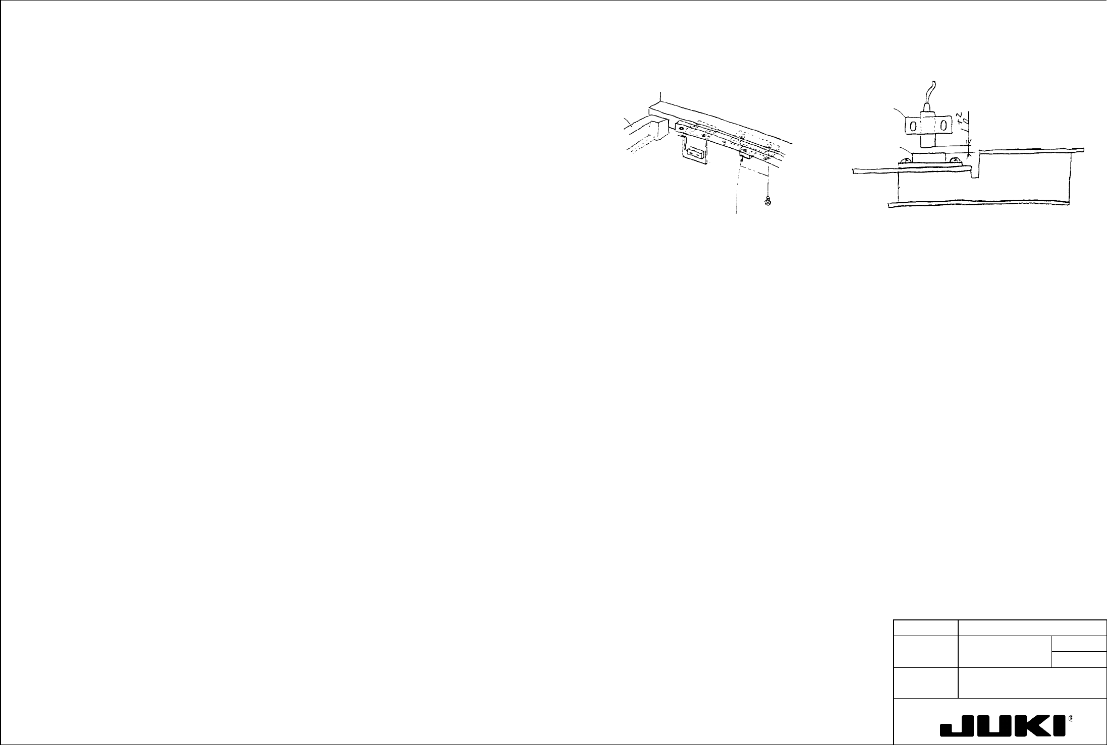
X-axis home position sensor
1) Let the transport mechanism clamp the square adjusting jig PWB.
X-MSC bracket
X home position senso
r
Magnetic switch
magnet
(furnished screw)
E94907250A0
X home position sensor
X frame end L
2) Perform home return motion only of YL motor.
3) Through teaching operation, set one side of the jig so that it runs parallel with Y-axis and check that the X-direction motion
is 0.01 or less on both ends of the jig.
4) 0.01 or more:
With the servo in free state, loosen the screw that secures X frame end L/R to LM guide and move X frame end L/R as
necessary to make the squareness below 0.03. When the value is attained, tighten the screw.
Next, move the head plate in X-direction to check that it is square to 0.01 or less with respect to the jig. Then, go back to
step 2).
4') Less than 0.01:
Go to step 5).
5) Perform home return operation again only of the YL motor.
6) Through teaching operation, move X-axis from the rear end of Y to the front. Move the sensor bracket as necessary so
that the right home position sensor is activated at the same time when the left one is activated.
Check procedure:
Move the head plate from the right-hand side of X-axis towards left and check that the clearance between the magnetic
switch magnet mounted on the X-MSC bracket and the X home position sensor measures 1 +2/0 mm.
7) Through teaching, check again that the left and right home position sensors are activated at the same time. (The
difference between right and left should be 1 pulse or less.)
Adjustment procedure:
Loosen the furnished screw that secures the home position sensor and adjust to obtain the clearance of 1 +2/0 mm from
the magnetic switch magnet.
8) Perform the normal home return operation. Then, check that the X-direction movement is square to 0.03 or less on both
ends of the jig PWB placed in parallel with the Y-axis.
FUNCTION NAME Limit Sensor Position Function/Performance CHECK/ADJUSTMENT METHODS (REMEDIAL ACTION PROCEDURE)
ASSURED QUALITY Reliability
QUALITY CHARACTERISTICS (SPECIFICATION VALUES) CATEGORY Safety
Product Image
ROLE IN FUNCTION (MEANING OF SPECIFICATION VALUES)
POSSIBLE MALFUNCTIONS (CAUSED BY INCORRECT SPECIFICATION VALUES)
COMPONENTS
NO. Part No. Part Name Associated Quality Characteristics
1
2
3 MODEL KE-750/760
4 UNIT X-Y Unit REF. NO.
5
NAME
XY-9
6 FUNCTION Limit Sensor Position
7
NAME
8
9
10
QA Table
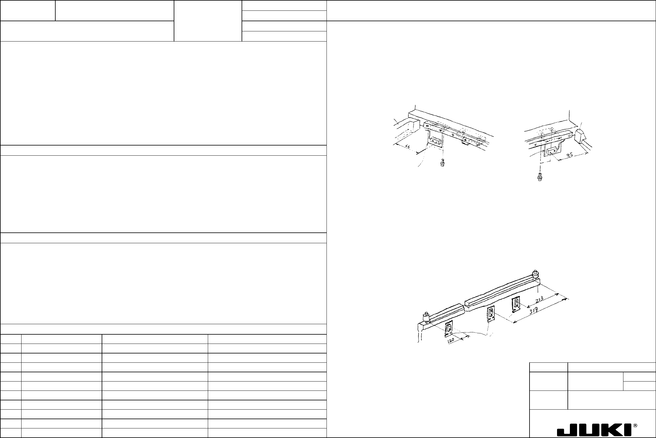
- X-axis limit sensor
X-axis limit
- Loosen the screw that secures the X-LMT bracket and move it as necessary so that the distance between the stopper
rubber mounting surface of X frame end L/R and the center of sensor measures 66/85 mm.
– Distance between the stopper rubber mounting surface of X frame end L and the center of sensor: 66 mm
– Distance between the stopper rubber mounting surface of X frame end R and the center of sensor: 85 mm
- For the crosswise direction, adjust so that the clearance between the X-MSC bracket mounted on the head plate and
the sensor surface measures 1 mm (when a spacer is used).
– Clearance between the X-MSC bracket and limit sensor surface: 1 mm
Y-axis limit
– Front: Distance between the LM guide rail front end face and the center of sensor: 120 mm
X frame end L
E2435725000
X-LMT bracket
SL603892TN
Tightening torque 1 Nm
E2435725000
X-LMT bracket
SL603892TN
Tightening torque 1 Nm
X frame end R
– Rear: Distance between the LM guide rail rear end face and the center of sensor: 213 mm
– Center (feeder detection): Distance between the LM guide rail rear end face and the center of sensor: 319 mm
– Clearance between the Y-ORG bracket and limit sensor surface: 1 mm
– Y-axis limit sensor
- Loosen the screw that secures the Y-LMT bracket and adjust so that the center of the sensor is located at:
120 mm from the LM guide front end face,
213 mm and 319 mm from the LM guide rear end face.
- Loosen the mounting screw of the Y-ORG bracket mounted on X frame end L and adjust so that the clearance between
the sensor surface and Y-ORG bracket becomes 1 mm (as using a spacer). Note that the Y-ORG bracket is fairly
long: check parallelism with Y-axis and ensure that the clearance from the limit sensor is uniform at any point.
E2324725000
Y-LMT bracket
LM guide rail
FUNCTION NAME DC Power Source Output Voltage Function/Performance CHECK/ADJUSTMENT METHODS (REMEDIAL ACTION PROCEDURE)
ASSURED QUALITY Reliability
QUALITY CHARACTERISTICS (SPECIFICATION VALUES) CATEGORY Safety
Product Image
ROLE IN FUNCTION (MEANING OF SPECIFICATION VALUES)
POSSIBLE MALFUNCTIONS (CAUSED BY INCORRECT SPECIFICATION VALUES)
COMPONENTS
NO. Part No. Part Name Associated Quality Characteristics
1 E16017250A0 Power source unit assembly
2
3 MODEL KE-750/760
4 UNIT Electrical REF. NO.
5
NAME
EL-1
6 FUNCTION DC Power Source Output
7
NAME Voltage
8
9
10
QA Table
The DC power source output voltage is to be measured at the DC power source supply pin on the back board of control unit.
Since the control unit does not use +6 VDC, however, the J3 connector of the power unit is to be used for the measurement.
[TB6-1, 2 (+6 V) and TB6-3, 4 (GND) may be used instead.]
No. Power source code Test pin on back board Set voltage value
1 PS1 A01 (+5 V) and A02 (GND) +5.15 to 5.2V
2 PS2 Pin 1 (+6 V) and pin 6 (GND) of connector J3 of power panel +6.3 to 6.5V
Turn the output voltage variable resistor of each DC power source to obtain the specified value for the DC power source output
voltage.
3 PS3 A34 (+24 V) and A33 (COM) +24V ± 0.1V
4 PS4 A04 (+12 V) and A06 (GND) +12V ± 0.1V
5 PS5 A04 (-12 V) and A06 (GND) -12V ± 0.1V
To ensure correct operations of all electrical circuits.
– Electrical circuit malfunction
– Defective electrical circuit