KE-750_QA表.pdf - 第59页
FUNCTION NAME X/Y Servo Driver Parameters (KE750) Function/Performance CHECK/ADJUSTMENT METHODS (REMEDIAL ACT ION PROCEDURE) ASSURED QUALITY Reliability QUALITY CHARACTERISTI CS (SPECIFIC ATION VALUES) CATEGORY Safety Pr…
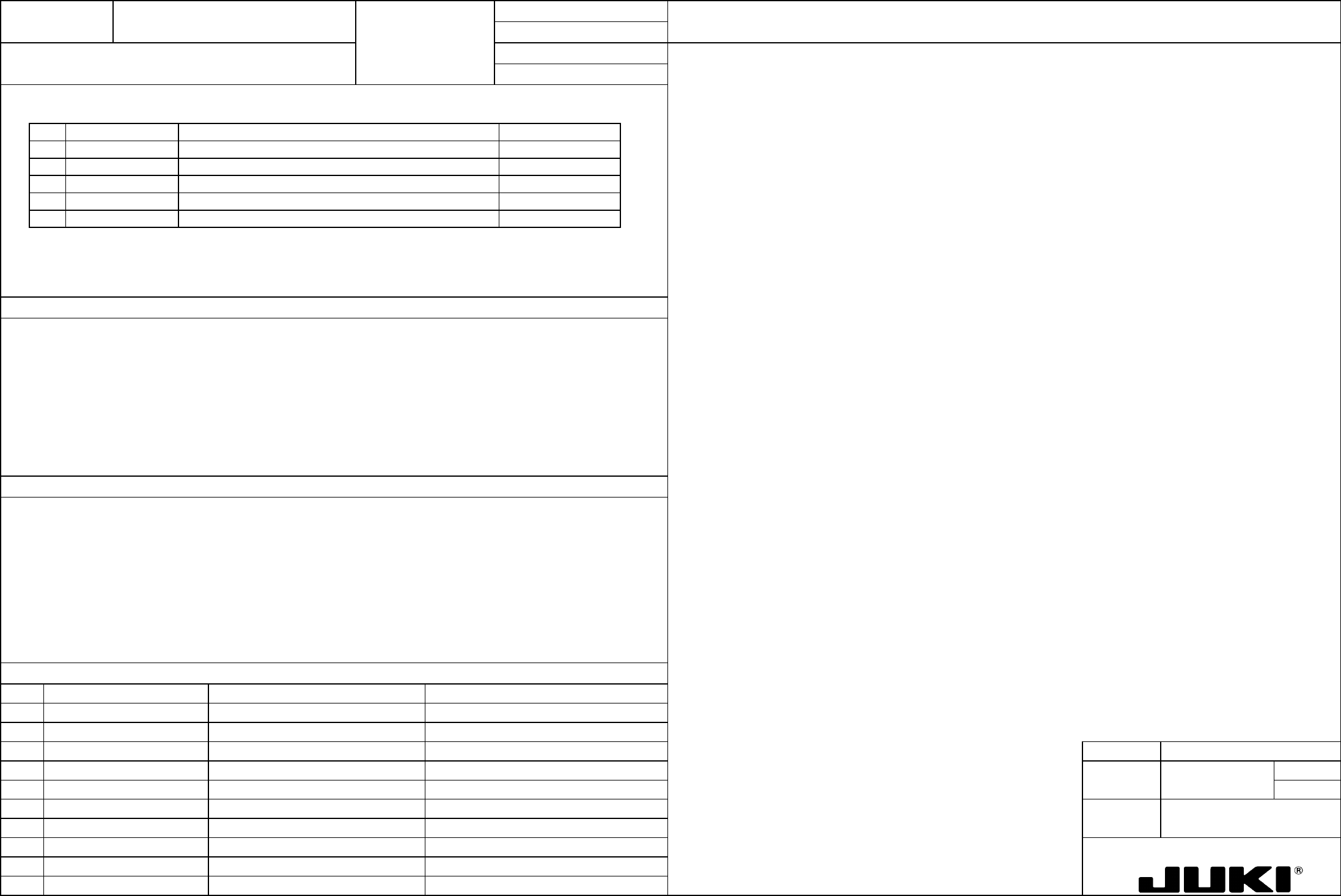
FUNCTION NAME DC Power Source Output Voltage Function/Performance CHECK/ADJUSTMENT METHODS (REMEDIAL ACTION PROCEDURE)
ASSURED QUALITY Reliability
QUALITY CHARACTERISTICS (SPECIFICATION VALUES) CATEGORY Safety
Product Image
ROLE IN FUNCTION (MEANING OF SPECIFICATION VALUES)
POSSIBLE MALFUNCTIONS (CAUSED BY INCORRECT SPECIFICATION VALUES)
COMPONENTS
NO. Part No. Part Name Associated Quality Characteristics
1 E16017250A0 Power source unit assembly
2
3 MODEL KE-750/760
4 UNIT Electrical REF. NO.
5
NAME
EL-1
6 FUNCTION DC Power Source Output
7
NAME Voltage
8
9
10
QA Table
The DC power source output voltage is to be measured at the DC power source supply pin on the back board of control unit.
Since the control unit does not use +6 VDC, however, the J3 connector of the power unit is to be used for the measurement.
[TB6-1, 2 (+6 V) and TB6-3, 4 (GND) may be used instead.]
No. Power source code Test pin on back board Set voltage value
1 PS1 A01 (+5 V) and A02 (GND) +5.15 to 5.2V
2 PS2 Pin 1 (+6 V) and pin 6 (GND) of connector J3 of power panel +6.3 to 6.5V
Turn the output voltage variable resistor of each DC power source to obtain the specified value for the DC power source output
voltage.
3 PS3 A34 (+24 V) and A33 (COM) +24V ± 0.1V
4 PS4 A04 (+12 V) and A06 (GND) +12V ± 0.1V
5 PS5 A04 (-12 V) and A06 (GND) -12V ± 0.1V
To ensure correct operations of all electrical circuits.
– Electrical circuit malfunction
– Defective electrical circuit

FUNCTION NAME X/Y Servo Driver Parameters (KE750) Function/Performance CHECK/ADJUSTMENT METHODS (REMEDIAL ACTION PROCEDURE)
ASSURED QUALITY Reliability
QUALITY CHARACTERISTICS (SPECIFICATION VALUES) CATEGORY Safety
Product Image
ROLE IN FUNCTION (MEANING OF SPECIFICATION VALUES)
POSSIBLE MALFUNCTIONS (CAUSED BY INCORRECT SPECIFICATION VALUES)
COMPONENTS
NO. Part No. Part Name Associated Quality Characteristics
1 E9612721000 AC servo driver
2 KM000000030 800-W AC servo driver
3 MODEL KE-750/760
4 UNIT Electrical REF. NO.
5
NAME
EL-2
6 FUNCTION X/Y Servo Driver Parameters
7
NAME (KE750) 1/3
8
9
10
QA Table
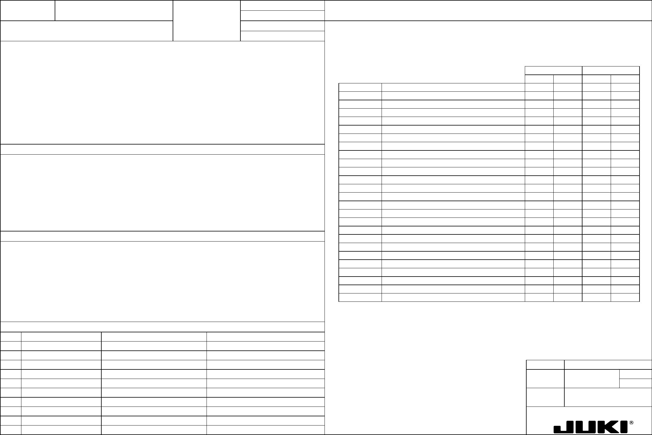
Setting values
See the adjustment procedure that follows.
See p. 3/3 for the setting procedure.
Serves as the control parameters of X/Y-axis motor, directly affecting the operation of X/Y-axis.
1. Degraded placement accuracy
2. Hunting and oscillation at stopping
3. Abnormal oscillation during operation
4. Degraded stopping accuracy
5. Servo driver alarm
KE 750
X-axis Y-axis
Parameter No. Name
0000 Control mode 0009 0009
0001 Position loop gain 1 0240 01C0
0002 Speed loop gain 1 0058 0040
0003 Speed loop integral time 1 0680 0680
0004 Not used — —
0005 Speed limit 1388 1388
0006 Current limit 007E 008A
0007 Imposition range 0004 0004
0008 Filter constant 7FFF 7FFF
0009 to 000b Not used — —
000C Speed alarm 13EC 13EC
000d Not used — —
000E Frequency divider/multiplier setting 0080 0080
000F CTRLSW (control operation selector switch) 0186 0186
0010 Monitor address setting 0030 0030
0011 Overload alarm level 0037 003C
0012 External encoder resolution 02A3 02A3
0013 Position loop gain 2 0220 0180
0014 Speed loop gain 2 0040 0028
0015 Speed loop integral time 2 0480 0500
0016 Not used — —
0017 Position loop gain gradient 0002 0030
0018 Speed loop gain gradient 0018 0020
0019 Speed loop integral time gradient 0008 0030
001A to 001d Alarm history 1 to 4 0000 0000
FUNCTION NAME X/Y Servo Driver Parameters (KE760) Function/Performance CHECK/ADJUSTMENT METHODS (REMEDIAL ACTION PROCEDURE)
ASSURED QUALITY Reliability
QUALITY CHARACTERISTICS (SPECIFICATION VALUES) CATEGORY Safety
Product Image
ROLE IN FUNCTION (MEANING OF SPECIFICATION VALUES)
POSSIBLE MALFUNCTIONS (CAUSED BY INCORRECT SPECIFICATION VALUES)
COMPONENTS
NO. Part No. Part Name Associated Quality Characteristics
1 E9612721000 AC servo driver
2 KM000000030 800-W AC servo driver
3 MODEL KE-750/760
4 UNIT Electrical REF. NO.
5
NAME
EL-2
6 FUNCTION X/Y Servo Driver Parameters
7
NAME (KE760) 2/3
8
9
10
QA Table
Setting values
See the adjustment procedure that follows.
See p. 3/3 for the setting procedure.
Serves as the control parameters of X/Y-axis motor, directly affecting the operation of X/Y-axis.
1. Degraded placement accuracy
2. Hunting and oscillation at stopping
3. Abnormal oscillation during operation
4. Degraded stopping accuracy
5. Servo driver alarm
KE 760
X-axis Y-axis
Parameter No. Name
0000 Control mode 0009 0009
0001 Position loop gain 1 0230 0200
0002 Speed loop gain 1 0058 0040
0003 Speed loop integral time 1 0680 0680
0004 Not used — —
0005 Speed limit 1388 1388
0006 Current limit 007E 008A
0007 Imposition range 0004 0004
0008 Filter constant 7FFF 7FFF
0009 to 000b Not used — —
000C Speed alarm 13EC 13EC
000d Not used — —
000E Frequency divider/multiplier setting 0080 0080
000F CTRLSW (control operation selector switch) 0186 0186
0010 Monitor address setting 0030 0030
0011 Overload alarm level 0037 003C
0012 External encoder resolution 02A3 02A3
0013 Position loop gain 2 0210 01C0
0014 Speed loop gain 2 0040 0028
0015 Speed loop integral time 2 0480 0540
0016 Not used — —
0017 Position loop gain gradient 0002 0060
0018 Speed loop gain gradient 0018 0040
0019 Speed loop integral time gradient 0008 0040
001A to 001d Alarm history 1 to 4 0000 0000