KE-750_QA表.pdf - 第65页
MODEL KE-750/760 UNIT Electrical REF. NO. NAME EL-4 FUNCTION Z-Axis/ θ -Axis Servo Driver NAME Parameters 2/8 QA Table Setting values Setting procedure: Parameters on screen mode 5 Connect remote operator model RP-001 ma…
FUNCTION NAME Z-Axis/θ-Axis Servo Driver Parameters Function/Performance CHECK/ADJUSTMENT METHODS (REMEDIAL ACTION PROCEDURE)
ASSURED QUALITY Reliability
QUALITY CHARACTERISTICS (SPECIFICATION VALUES) CATEGORY Safety
Product Image
ROLE IN FUNCTION (MEANING OF SPECIFICATION VALUES)
POSSIBLE MALFUNCTIONS (CAUSED BY INCORRECT SPECIFICATION VALUES)
COMPONENTS
NO. Part No. Part Name Associated Quality Characteristics
1 KM000000070 30-W AC servo multi-axis unit (4-axis)
2 KM000000080 30-W AC servo multi-axis unit (2-axis)
3 MODEL KE-750/760
4 UNIT Electrical REF. NO.
5
NAME
EL-4
6 FUNCTION Z-Axis/θ-Axis Servo Driver
7
NAME Parameters 1/8
8
9
10
QA Table
Setting values
See the adjustment procedure that follows.
Parameters in screen mode 0
See p. 2/8 and onward for the setting procedure.
Page no. Abbreviation Name Z-axis
θ-axis
0 Kp Position loop gain — —
1 Kff Feed forward gain — —
2 Kvp Speed loop proportional gain 100 50
3 Tvi Speed loop integral time constant 20 10
4 INP Positioning completion signal width — —
5 OVF Excessive deviation value — —
6 EGER Electronic gear ratio — —
7 ENCR Output pulse dividing ratio 1/2 1/1
8 LTG Low speed 50 50
9 PMOD Command pulse train configuration — —
Serves as the control parameters of Z/$-axis, directly affecting the operation of Z/$-axis.
10 SSW1 Selector switch 1 00000000 00000000
11 SSW2 Selector switch 2 00000001 00000000
12 VLPF Speed command LPF 500 500
13 ILPF Current command LPF 500 500
14 Tacc Speed command acceleration/deceleration time 0 0
15 Tpcm Position command acceleration/deceleration time
constant
— —
16 Scal Speed scale 2000 4000
Parameters in screen mode 1
1. Degraded placement accuracy
2. Pickup failure, standing chip error
Page no. Abbreviation Name
Common to Z/θ-axis
3. ATC nozzle change error
0 TYPE Control mode Velocity
4. Oscillation at stopping
1 ENKD Encoder type INC.E
5. Servo driver alarm
2 ENPL No. of encoder pulses 2000 P/R
3 MOT Motor type P50B03003P
4 CABLE Applicable cable length 0 - -5m
A dash "-" in the setting value column indicates that the parameter is not used, requiring no setting.
MODEL KE-750/760
UNIT Electrical REF. NO.
NAME
EL-4
FUNCTION Z-Axis/θ-Axis Servo Driver
NAME Parameters 2/8
QA Table
Setting values Setting procedure:
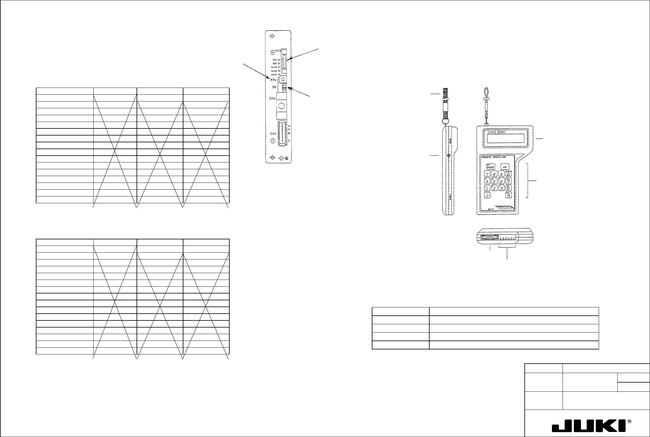
Parameters on screen mode 5 Connect remote operator model RP-001 manufactured by Sanyo Denki Co., Ltd. to CN3 on the front of the servo driver
and make the parameter settings.
Set the parameters and set RSW on the front face of driver to "0." (See fig. on the right.)
Check pin
Control keys
Connector to amplifier
LCD panel (16
characters x 2 lines)
Brightness control
Hand-carrying band
Outline of Remote Operator:
The illustration below sketches a remote operator.
Z-axis
Gain Setting Switches and Gain Setting Values
Gain setting switch Kp Kvp Tvi
0 Kp: 0 ( 10) Kvp: 0 ( 100) Tvi: 0 ( 20)
1 Kp:1 ( 10) Kvp: 1 ( 20) Tvi: 1 ( 20)
2 Kp: 2 ( 20) Kvp: 2 ( 35) Tvi: 2 ( 50)
3 Kp: 3 ( 20) Kvp: 3 ( 35) Tvi: 3 ( 50)
4 Kp: 4 ( 30) Kvp: 4 ( 50) Tvi: 4 ( 50)
5 Kp: 5 ( 30) Kvp: 5 ( 50) Tvi: 5 ( 20)
6 Kp: 6 ( 30) Kvp: 6 ( 70) Tvi: 6 ( 50)
7 Kp: 7 ( 30) Kvp: 7 ( 70) Tvi: 7 ( 20)
8 Kp: 8 ( 45) Kvp: 8 ( 100) Tvi: 8 ( 50)
9 Kp: 9 ( 45) Kvp: 9 ( 100) Tvi: 9 ( 20)
A Kp: A ( 45) Kvp: A ( 140) Tvi: A ( 50)
B Kp: B ( 45) Kvp: B ( 140) Tvi: B ( 20)
C Kp: C ( 60) Kvp: C ( 200) Tvi: C ( 50)
D Kp: D ( 45) Kvp: 9 ( 200) Tvi: D ( 20)
E Kp: E ( 60) Kvp: E ( 280) Tvi: E ( 50)
F Kp: F ( 60) Kvp: F ( 280) Tvi: F ( 20)
θ-axis
Gain Setting Switches and Gain Setting Values
Gain setting switch Kp Kvp Tvi
0 Kp: 0 ( 10) Kvp: 0 ( 50) Tvi: 0 ( 10)
1 Kp:1 ( 10) Kvp: 1 ( 20) Tvi: 1 ( 20)
2 Kp: 2 ( 20) Kvp: 2 ( 35) Tvi: 2 ( 50)
3 Kp: 3 ( 20) Kvp: 3 ( 35) Tvi: 3 ( 50)
4 Kp: 4 ( 30) Kvp: 4 ( 50) Tvi: 4 ( 50)
5 Kp: 5 ( 30) Kvp: 5 ( 50) Tvi: 5 ( 20)
6 Kp: 6 ( 30) Kvp: 6 ( 70) Tvi: 6 ( 50)
7 Kp: 7 ( 30) Kvp: 7 ( 70) Tvi: 7 ( 20)
8 Kp: 8 ( 45) Kvp: 8 ( 100) Tvi: 8 ( 50)
9 Kp: 9 ( 45) Kvp: 9 ( 100) Tvi: 9 ( 20)
A Kp: A ( 45) Kvp: A ( 140) Tvi: A ( 50)
B Kp: B ( 45) Kvp: B ( 140) Tvi: B ( 20)
C Kp: C ( 60) Kvp: C ( 200) Tvi: C ( 50)
D Kp: D ( 45) Kvp: 9 ( 200) Tvi: D ( 20)
E Kp: E ( 60) Kvp: E ( 280) Tvi: E ( 50)
F Kp: F ( 60) Kvp: F ( 280) Tvi: F ( 20)
Place this switch in
the upper position
when making
parameter settings.
Fig. 7-1 Remote Operator
Table 7-1 Remote Operator Specifications
Item Specifications
Power source Supplied by servo amplifier
Connection Connector with a 2-m-long dedicated cable
Ambient temperature Operating: 0 to +50°C | Storage: -20 to +70°C
Operating ambience No oil mist, corrosive gas, and dust allowed.
Note:
An X in the setting value column indicates that the parameter is not used, requiring no setting.
Handle with care, as dropping the unit can damage the LCD panel.
MODEL KE-750/760
UNIT Electrical REF. NO.
NAME
EL-4
FUNCTION Z-Axis/θ-Axis Servo Driver
NAME Parameters 3/8
QA Table
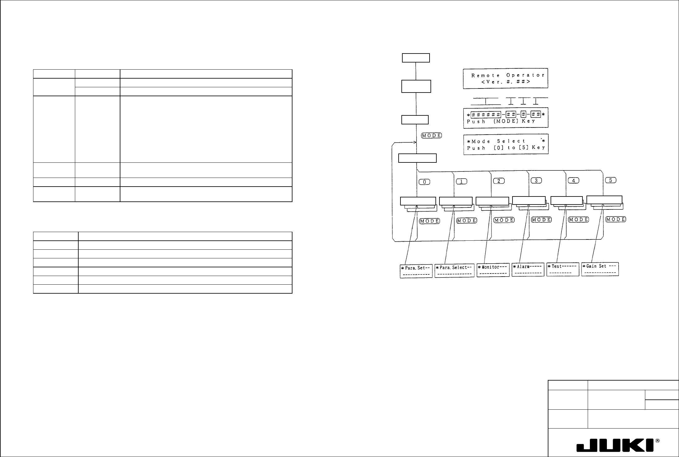
Remote Operator
- Basic Operating Procedure
Function Table
Control
method
Amplifier
capacity
Motor code
CPU version
Selected
screen
displays
Gain setting screen
Test screenAlarm trace screen
Select screen Monitor screenKey input screen
Mode select screen
Initial screen
In commu-
nication
Power ON
Table 7-2 Remote Operator Functions
Mode Screen no. Function
Setting mode 0 Directly enter the user parameter from the keyboard.
1 Select the user parameter according as instructed on the screen.
Monitor mode 2 Shows various monitors on the screen:
- Status monitor
- Input monitor
- Output monitor
- Speed command
- Speed
- Current command
- Position deviation counter value
Alarm trace
mode
3 Displays the current and past seven alarms.
Test mode 4 Allows for jog operation and servo tuning.
Gain setting
mode
5 Sets the gain (Kp, Kvp, Tvi) as determined with the rotary switch on
the amplifier front panel.
Table 7-3 Remote Operator Check Pin Functions
Name Description
VCMD Monitors the speed command (CN1 to 19 pin inputs).
M1 Monitors the same outputs as the amplifier speed monitor outputs.
M2 Monitors the same outputs as the amplifier torque monitor outputs.
SG Signal ground (common to amplifier SG).
DM1 Not used
DM2 Not used
Fig. 7-2 Remote Operator Basic Operation
Note:
If the operator is not operated for about 3 minutes, the LCD display goes out. To restart it, press the MODE key.