KE-750_QA表.pdf - 第68页
MODEL KE-750/760 UNIT Electrical REF. NO. NAME EL-4 FUNCTION Z-Axis/ θ -Axis Servo Driver NAME Parameters 5/8 QA Table Parameter selecting mode (screen mode 1) W hen in this mode, you select paramet ers according as inst…
MODEL KE-750/760
UNIT Electrical REF. NO.
NAME
EL-4
FUNCTION Z-Axis/θ-Axis Servo Driver
NAME Parameters 4/8
QA Table
(Setting Exercise)
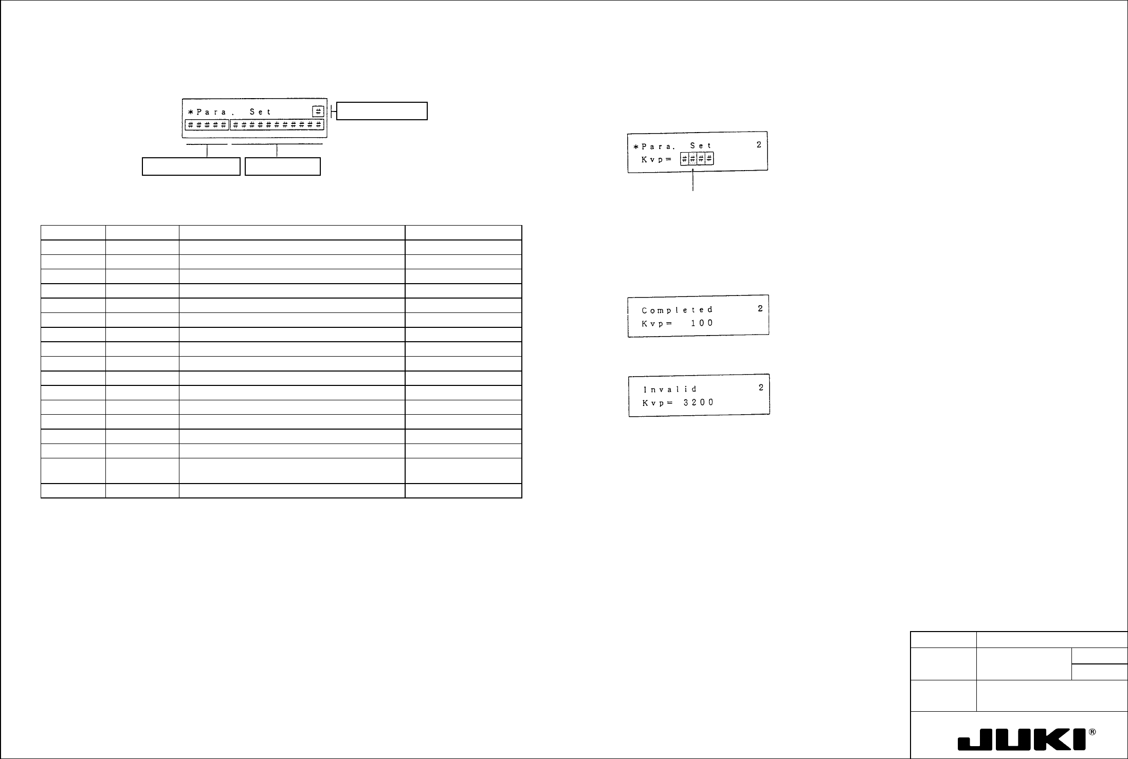
Parameter setting mode (screen mode 0)
Let's set, for example, the speed loop proportional gain to 100.
When in this mode, you directly operate the keys to set the data.
Setting value dataParameter abbreviation
Screen page number
Step 1. Select page 2 with ↓ or ↑.
Cursor blinks.
Table 7-4 Screen Mode 0 Parameters
Page no. Abbreviation Name Setting range
Step 2. Using > or <, move the cursor to the digit to be entered.
0 Kp Position loop gain 1 to 255
Step 3. Using numeric keys 0 to 9, enter 100 consecutively.
Step 4. Press WR to store the data in nonvolatile memory, and the system works based on the set data.
1 Kff Feed forward gain 0 to 100
2 Kvp Speed loop proportional gain 10 to 3000
When the setting is completed, the following message appears:
3 Tvi Speed loop integral time constant 2 to 1000
4 INP Positioning completion signal width 1 to 9999
5 OVF Excessive deviation value 1 to 32767
6 EGER Electronic gear ratio 1/10000 to less than 32
7 ENCR Output pulse dividing ratio 1/1 to 1/8192
If a value has been entered that falls outside the setting range, the following message appears and the
remote operator does not bother storing the data in memory. Start the procedure over with step 2.
8 LTG Low speed 10 to 9999
9 PMOD Command pulse train configuration 0.1
10 SSW1 Selector switch 1 0.1
3200 Hz has been entered:
11 SSW2 Selector switch 2 0.1
12 VLPF Speed command LPF 1 to 500
13 ILPF Current command LPF 1 to 500
Step 5. Press MODE to go back to the initial screen.
14 Tacc Speed command acceleration/deceleration time 0 to 255
To set for another page, repeat steps from step 2.
15 Tpcm Position command acceleration/deceleration time
constant
0 to 100
Note: If the selector switch (SW) on the amplifier front panel is in the lower position, it is impossible to change the settings of
parameters (Kp, Kvp, Tvi) on page nos. 0, 2, and 3 from the remote operator. The parameter displayed at this time is
that determined with the gain setting switch (RSW) on the amplifier front panel. [See the description on gain setting
mode (screen mode 5).]
16 Scal Speed scale 900 to 6666
MODEL KE-750/760
UNIT Electrical REF. NO.
NAME
EL-4
FUNCTION Z-Axis/θ-Axis Servo Driver
NAME Parameters 5/8
QA Table
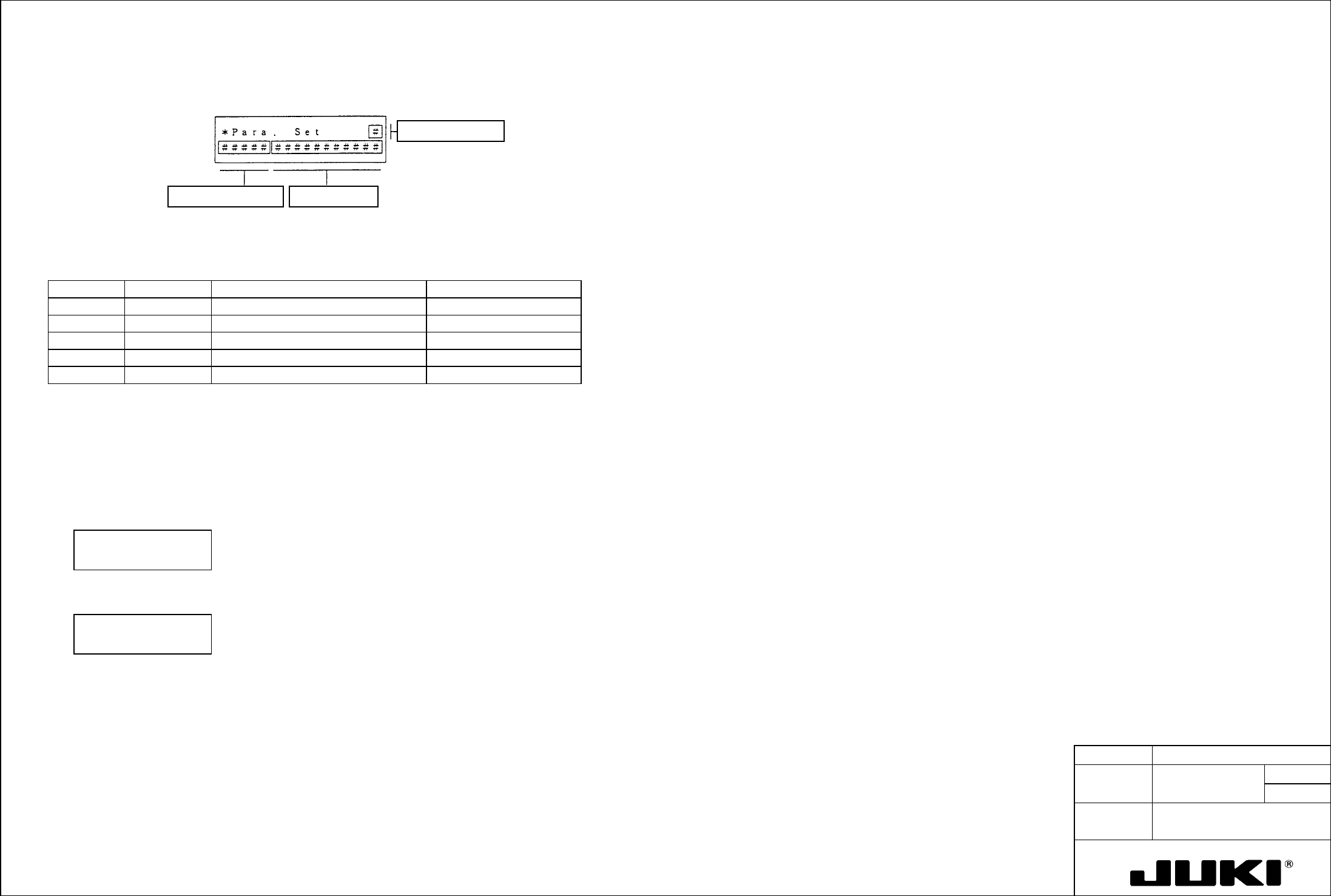
Parameter selecting mode (screen mode 1)
When in this mode, you select parameters according as instructed on the screen.
Contents of optionParameter abbreviation
Screen page number
Table 7-5 Screen Mode 1 Parameters
Page no. Abbreviation Name No. of options available
0 TYPE Control mode 2
1 ENKD Encoder type 1
2 ENPL No. of encoder pulses 1
3 MOT Motor type P30, P50 series
4 CABLE Applicable cable length 4
(Setting Exercise)
Let's change, for example, the amplifier control method from Position to Velocity.
Step 1. Select screen mode 1.
Step 2. Using
↓ or ↑, select page 0 and then, using > or <, select Velocity.
Then, the following message appears:
*Para. Select 0
TYPE: Velocity
Step 3. Press WR, and the following message appears:
* Completed 0
TYPE: Velocity
Step 4. Press MODE to go back to the initial screen.
To set for another page, repeat steps from step 2.
Notes:
- No data can be changed of mode 1 - 0, 3, and 4 unless bit 7 (SPC bit) of SSW2 (mode 0 - 11) has first been set to
"1."
The new setting made becomes valid only after power is turned OFF.
- Pages 1 and 2 only monitor the current setting values and do not allow the setting to be changed.
MODEL KE-750/760
UNIT Electrical REF. NO.
NAME
EL-4
FUNCTION Z-Axis/θ-Axis Servo Driver
NAME Parameters 6/8
QA Table
(Setting Exercise)
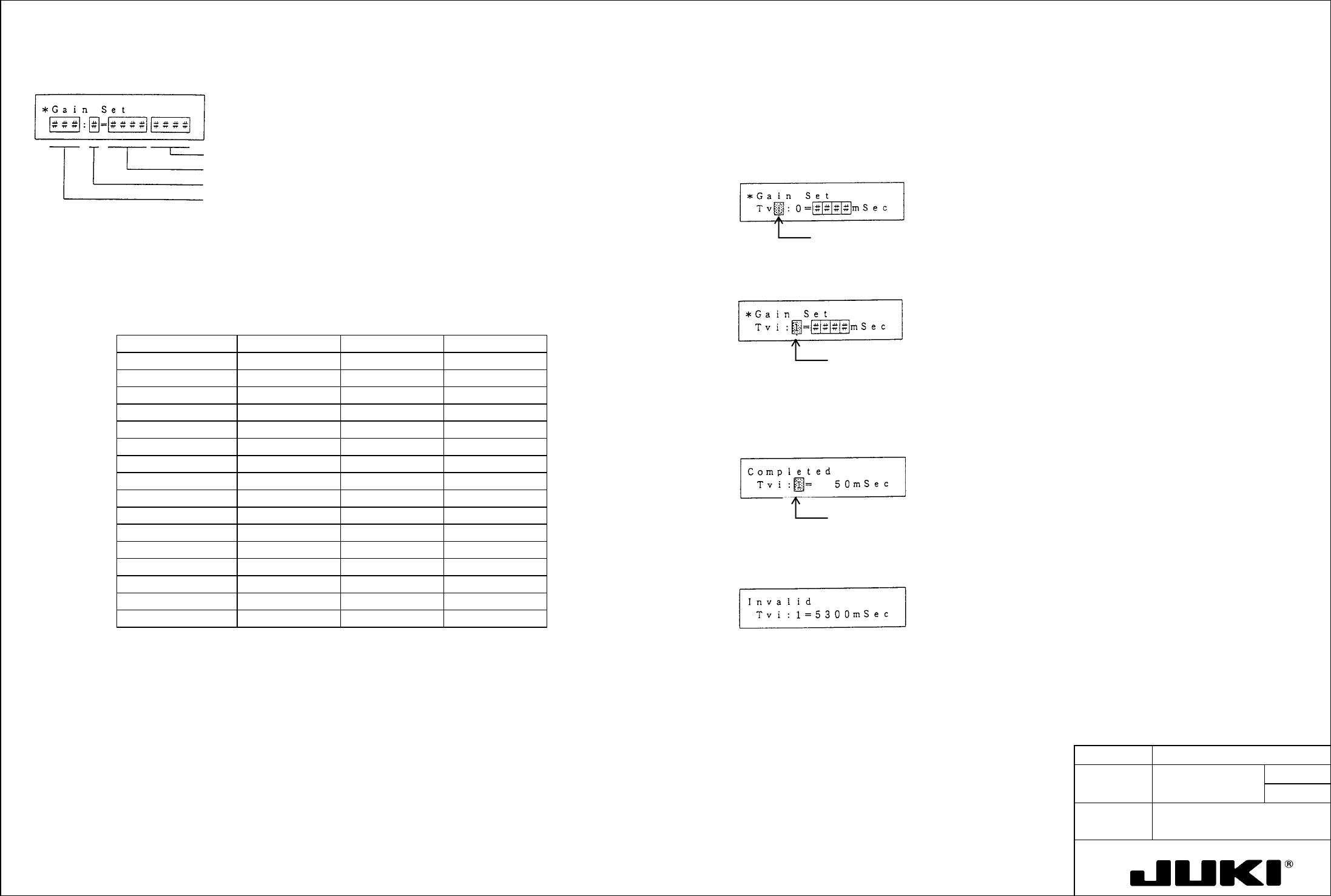
Gain setting mode (screen mode 5)
Let's set, for example, Tvi:1 to 50 msec.
Unit
Setting value data
Gain setting switch (RSW) value 0 to F
Parameter type Kp, Kvp, Tvi
Step 1. Set bit 7 of SSW2 to "1."
Return the mode select screen and select screen mode 5.
Step 2. Using > or <, move the cursor to the desired parameter type and, using
↓ or ↑, select Tvi.
Cursor blinks.
When in this mode, you can change the parameter (Kp, Kvp, Tvi) corresponding to the value set with the gain setting switch
(RSW) when the selector switch (SW) on the amplifier front panel is placed in the upper position to any desired value. The
following table shows the relation between the gain setting switch and the set parameter.
Step 3. Using > or <, move the cursor to the gain setting switch value and, using ↓ or ↑, select 1.
Table 7-9 Gain Setting Switch and Gain Setting Values
(Figures in parentheses are factory settings.)
Cursor blinks.
Gain setting switch Kp Kvp Tvi
0 Kp: 0 ( 10) Kvp: 0 ( 100) Tvi: 0 ( 20)
1 Kp:1 ( 10) Kvp: 1 ( 20) Tvi: 1 ( 20)
Step 4. Using > or <, move the cursor to the digit of the setting data in which you want to enter a value.
2 Kp: 2 ( 20) Kvp: 2 ( 35) Tvi: 2 ( 50)
Step 5. Using the numeric keys 0 to 9, enter "50" consecutively.
3 Kp: 3 ( 20) Kvp: 3 ( 35) Tvi: 3 ( 50)
Step 6. Press WR to store the data in nonvolatile memory.
4 Kp: 4 ( 30) Kvp: 4 ( 50) Tvi: 4 ( 50)
When the data has been set, the following message appears:
5 Kp: 5 ( 30) Kvp: 5 ( 50) Tvi: 5 ( 20)
Cursor blinks.
6 Kp: 6 ( 30) Kvp: 6 ( 70) Tvi: 6 ( 50)
7 Kp: 7 ( 30) Kvp: 7 ( 70) Tvi: 7 ( 20)
8 Kp: 8 ( 45) Kvp: 8 ( 100) Tvi: 8 ( 50)
9 Kp: 9 ( 45) Kvp: 9 ( 100) Tvi: 9 ( 20)
A Kp: A ( 45) Kvp: A ( 140) Tvi: A ( 50)
If a value has been entered that falls outside the setting range, the following message appears and the remote
operator does not bother storing the data in memory.
B Kp: B ( 45) Kvp: B ( 140) Tvi: B ( 20)
C Kp: C ( 60) Kvp: C ( 200) Tvi: C ( 50)
D Kp: D ( 45) Kvp: 9 ( 200) Tvi: D ( 20)
E Kp: E ( 60) Kvp: E ( 280) Tvi: E ( 50)
F Kp: F ( 60) Kvp: F ( 280) Tvi: F ( 20)
5300 msec. has
been entered:
Example:
Step 7. Press MODE to go back to the initial screen.
In the gain setting mode, make the following settings: Kp:1 = 30 rad/s., Kvp:1 = 70, and Tvi:1 = 30 msec. Then, place the
selector switch (SW) on the amplifier front panel in the upper position and set the gain setting switch (RSW) to "1." In this
condition:
To set another data, repeat steps from step 2.
The 30 rad/s value is set for Kp (position loop gain), 70 for Kvp (proportional gain), and 30 ms for Tvi (integral time
constant).
Note: BEFORE SETTING THE OPERATOR INTO THE GAIN SETTING MODE, be sure set bit 7 of SSW2 (mode 0 - 11) to
"1."