KE-750_QA表.pdf - 第74页
MODEL KE-750/760 UNIT Electrical REF. NO. NAME EL-6 FUNCTION Transport Stepping Motor Drive NAME Current 2/2 QA Table Specifications • Input power source: 20 to 40 VDC, 3 A max. • Drive current: 1.4 A/phase max. • Operat…
FUNCTION NAME Transport Stepping Motor Drive Current Function/Performance CHECK/ADJUSTMENT METHODS (REMEDIAL ACTION PROCEDURE)
ASSURED QUALITY Reliability
QUALITY CHARACTERISTICS (SPECIFICATION VALUES) CATEGORY Safety
Product Image
ROLE IN FUNCTION (MEANING OF SPECIFICATION VALUES)
POSSIBLE MALFUNCTIONS (CAUSED BY INCORRECT SPECIFICATION VALUES)
COMPONENTS
NO. Part No. Part Name Associated Quality Characteristics
1 HM001320000 Five-phase stepper driver DC power source output voltage adjustment
2
3 MODEL KE-750/760
4 UNIT Electrical REF. NO.
5
NAME
EL-6
6 FUNCTION Transport Stepping Motor Drive
7
NAME Current 1/2
8
9
10
QA Table
1. Before starting the adjustment procedure, make sure that the DC power source output voltage has been properly adjusted.
Drive current: 1.4 A ±0.005 A/phase
2. Turn the transport stepping motor and measure the voltage across [CP1]+ and [CP2]- on the five-phase stepper driver
with a digital voltmeter.
3. Slowly turn the RUN variable resistor so that the voltage across [CP1]+ and [CP2]- becomes 2.8 V ±0.01 V.
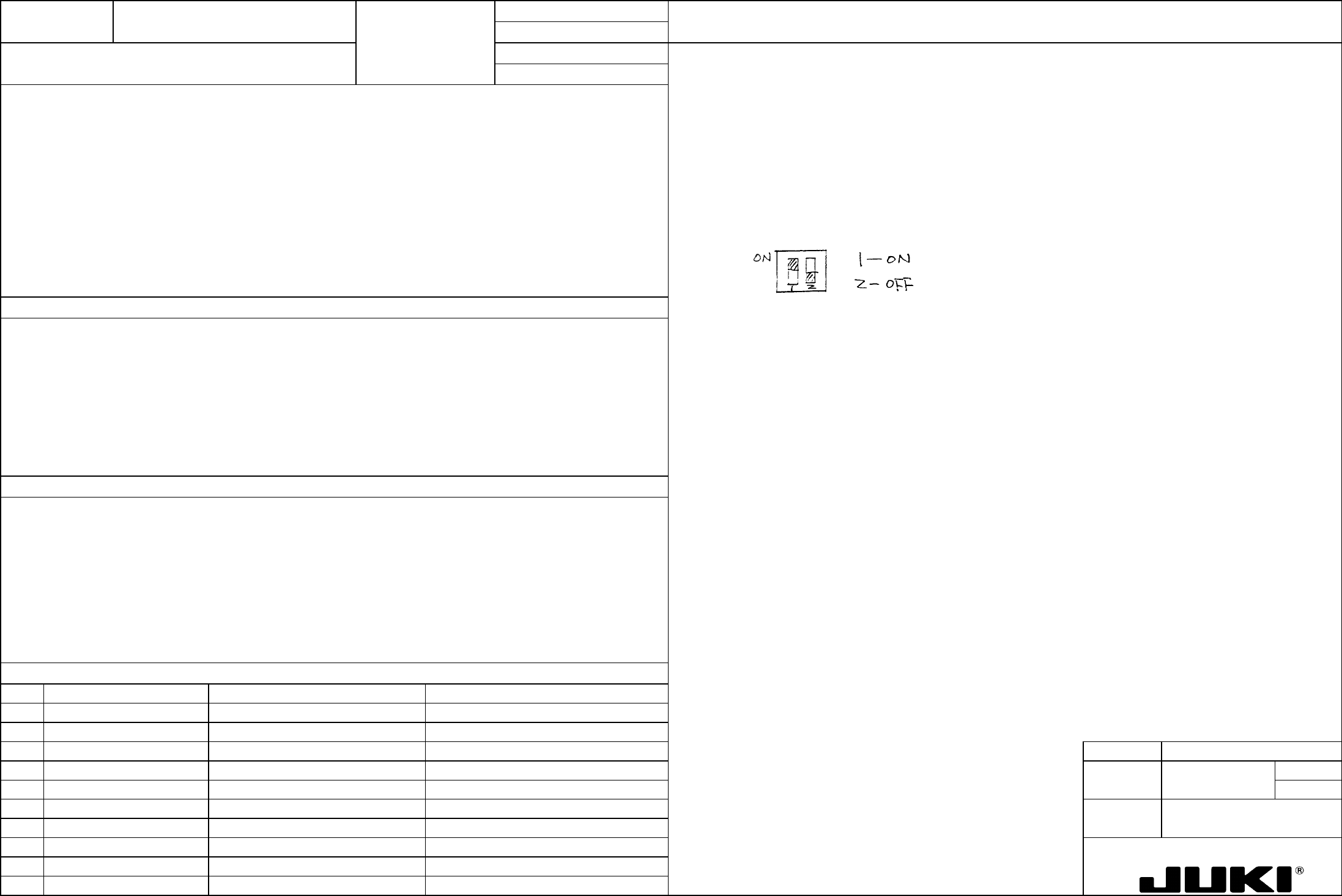
4. Flip the DIP switch keys as follows.
Directly concerned with the rotating torque of the transport stepping motor (centering buffer).
1. Stepping motor out of correct timing, resulting in a transport error.
2. Stepping motor temperature running abnormally high
MODEL KE-750/760
UNIT Electrical REF. NO.
NAME
EL-6
FUNCTION Transport Stepping Motor Drive
NAME Current 2/2
QA Table
Specifications • Input power source: 20 to 40 VDC, 3 A max.
• Drive current: 1.4 A/phase max.
• Operating temperature range: 0 to 40°C
• Weight: Approx. 100 g
DC20V
1.4A/Max
0 to 40°C
100g
RUN knob
POWER lamp
Power source
20 to 40 VDC
+5 V, 30 mA to
be supplied
User controlle
r
DIP switch
A
pplicable connector
CN1 60-8263-3068-15-000 (Elco)
CN2 60-8263-3108-15-000 (Elco)
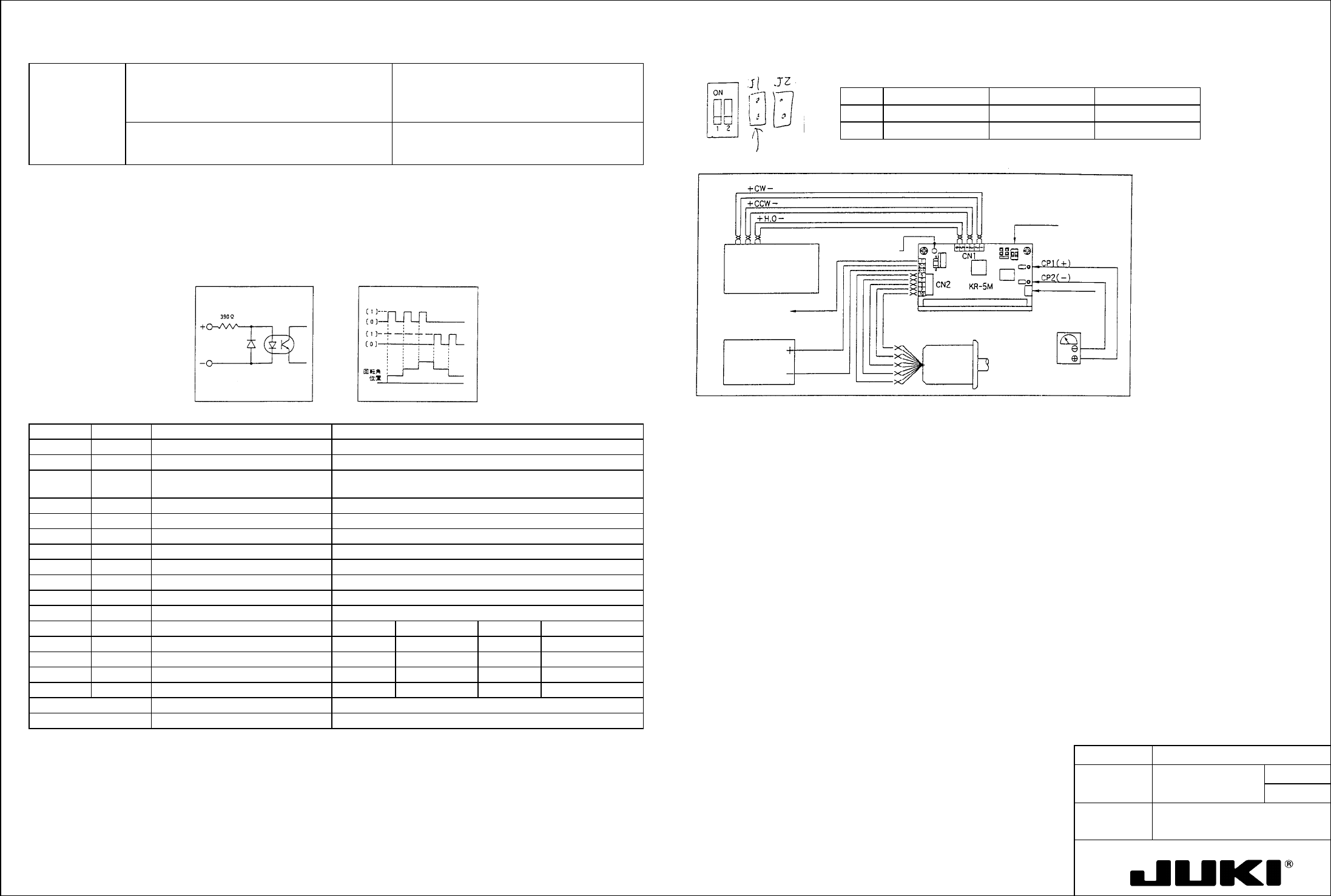
Wiring
diagram
Sanyo Motor specifications with this jumper removed.
No Mode ON OFF
1 Step angle 0.72 degrees/pulse 0.36 degrees/pulse
• Applicable motors: 5-phase stepping motor with -type five or ten
leads manufactured by Oriental Motor, Sanyo
Denki, Tamagawa Seiki, Minebea, etc.
Clock system 1-clock 2-clock
Input Pulse Characteristics
o Pulse width: 5
μs min.
o Pulse intervals: 5
μs min.
o Rise/fall time: 1
μs max.
o Max. pulse frequency: 50K PPS
o Pulse voltage: [1] 4 to 12 V, [0] 0.5 to -12 V
o Interval resistance: 390 ohms
Input timing chart Signal input circuit
I/O Signal Descriptions
Current Setting Procedure
Connector Pin no. Signal name Function
To allow the current in each of the following conditions to flow through the motor, connect a voltmeter across [CP1]+ and
[CP2]- and turn RUN control to set the voltage to the value obtained with the following formula.
CN1 1 CW+ (2-clock) Forward rotation signal input (2-clock)
2 CW– (2-clock) Pulse input at 1 clock
Check pin voltage (V) = Set current x 2
3 CCW+ (2-clock) Backward rotation signal input (2-clock) CW when [1]
Rotating direction input at 1 clock CCW when [0]
The current is factory-set to 1.4 A/phase.
4 CCW– (2-clock)
Setting and Handling Procedure:
5 H.O+ Motor energization OFF when [1]
[1] Before turning power ON, turn the RUN knob fully counterclockwise.
6 H.O–
[2] To supply the motor with the driving rated current, apply a forward or backward rotation signal with a frequency of 10 pps
or more and turn RUN knob slowly to set the calculated voltage.
CN2 1 +5V Max. 30 mA to be supplied
2 +V Drive power source 20 to 40 VDC
Note that the motor starts turning when the signal is applied.
3
[3] The current value set during auto current down is fixed at about 60% of the rated current.
4 GND Drive power source 0 V
[4] To free the motor shaft, set the H.O pin to [1]. This frees the motor even during rotation.
5
6 Motor wiring 5-lead Blue 10-lead Blue + black
Precautions for Use
Red Red + brown
• Keep the input signal line away from the power source and motor lines.
Orange Violet + orange
• Provide good ventilation if used within a cabinet.
• To install, face the mounting surface on the bottom of the main unit down and press it tightly up against metal.
Green Yellow + green
Black hite + gray
RUN knob Current setting variable resistor Adjust output current to motor.
Current down Auto current down Output current reduced down to about 60%
Note: Pin numbers are in order on the board.
DIP Switch Descriptions
FUNCTION NAME PWB Detection Sensor Sensitivity Function/Performance CHECK/ADJUSTMENT METHODS (REMEDIAL ACTION PROCEDURE)
ASSURED QUALITY Reliability
QUALITY CHARACTERISTICS (SPECIFICATION VALUES) CATEGORY Safety
Product Image
ROLE IN FUNCTION (MEANING OF SPECIFICATION VALUES)
POSSIBLE MALFUNCTIONS (CAUSED BY INCORRECT SPECIFICATION VALUES)
COMPONENTS
NO. Part No. Part Name Associated Quality Characteristics
1 E94637250A0 IN sensor cable assembly
2 E94657250A0 STOP sensor cable assembly
3 E94667250A0 C.OUT sensor cable assembly MODEL KE-750/760
4 E94677250A0 OUT sensor cable assembly UNIT Electrical REF. NO.
5 E94647250A0 WAIT sensor cable assembly
NAME
EL-7
6 FUNCTION PWB Detection Sensor
7
NAME Sensitivity 1/2
8
9
10
QA Table
Adjustment of reflector type sensors
The sensor shall be capable of detecting black glass epoxy PWBs with no gloss (no resist) and glass epoxy PWBs with green
resist on bottom surfaces and with no resist on R surfaces.
1. Turn the sensitivity adjustment knob of the sensor to the MIN position.
2. Place a black glass epoxy PWB with no gloss (no resist) on the transport rails above the sensor.
3. Slowly turn the sensitivity adjustment knob of the sensor clockwise from the MIN position and stop turning it when the
indicator lamp lights up.
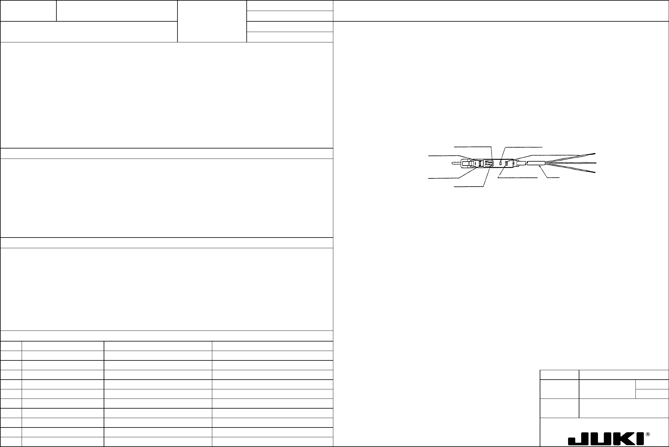
Adjustment of interrupter type sensor (WAIT sensor amplifier)
1. Switch setting
Place the L-ON/D-ON selector switch in the D-ON position.
Tuning button
L-ON/D-ON selector switch
Cord
Mode selector switch
Digital displa
y
Operation indicator lamp (red)
Stability indicator lamp (green)
Off delay indicator lamp
This adjustment ensures that the sensor detects PWBs of various colors and does not sense any object including the safety
cover other than PWBs.
1. PWB detection error while PWBs are being transported.