Galaxy EX ProFlow Module - 第10页
PROFLOW M ODULE ADJUSTMENTS AND SETTINGS 11. 10 Tech nical Ref erenc e Ma nual Ch apte r Issu e 4, Ju n 18 22. Usin g a sui ta ble str aig ht edg e, p lac e i t ac ros s on e c orn er o f th e c arr ier and the st e ncil…
PROFLOW MODULE
ADJUSTMENTS AND SETTINGS
Chapter Issue 4, Jun 18 Technical Reference Manual 11.9
10. Place the tooling top onto the tooling base, ensuring the tooling top dowel
pins are correctly located in the top of the tooling base.
11. Close the front printhead cover.
12. Press the System button.
13. Select Back.
14. Select Board Width.
15. Select Transport Height.
16. Place an empty known good flat carrier on the input conveyor.
17. Select Load Board, the carrier is driven into the board stop position.
18. Select Vision Height.
19. Select Print Height.
20. Select Open Cover Commands.
21. Open the front printhead cover.
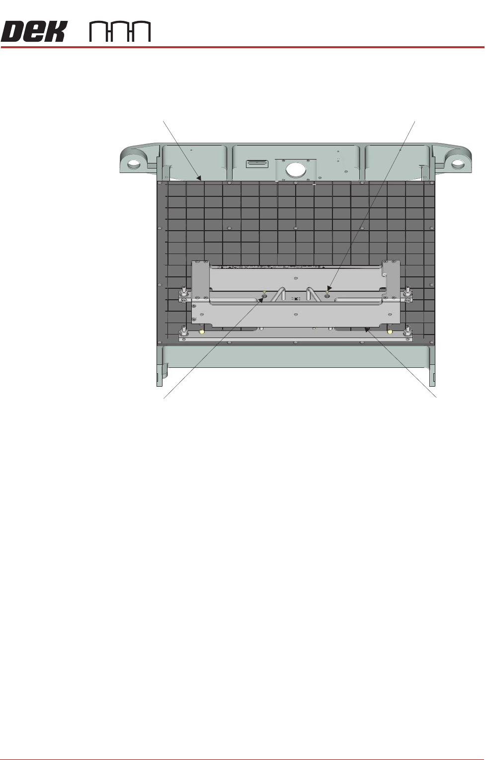
Manual Tooling Plate
Tooling Top
Tooling Top
Dowel Pin (in 2 Positions)
Tooling Base Dowel
Hole (in 2 Positions)
Front View on M anual Tooling Plate
PROFLOW MODULE
ADJUSTMENTS AND SETTINGS
11.10 Technical Reference Manual Chapter Issue 4, Jun 18
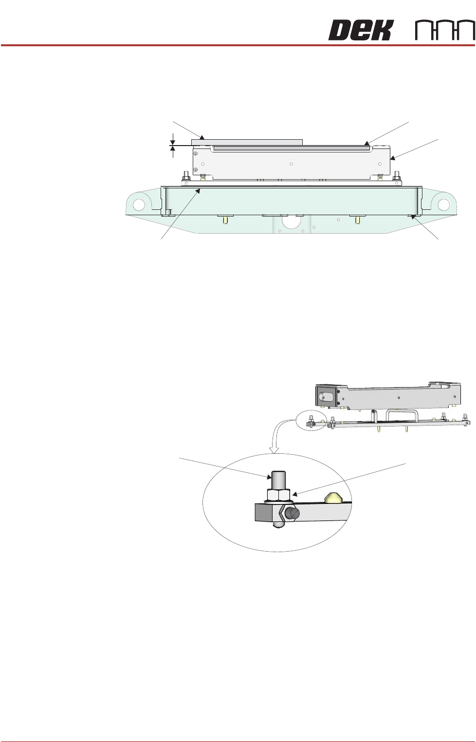
22. Using a suitable straight edge, place it across one corner of the carrier and
the stencil support and check levelness between the support and the car-
rier.
23. Ensure the gap between the stencil support and the carrier top face is less
than 0.05mm.
a. If adjustment is required, go to Step 24.
b. Or, if adjustment is not required, go to Step 31.
24. Loosen the tooling base foot locknut using a 13mm spanner.
25. Adjust the height of the foot as required using a 4mm Allen key.
26. Recheck the gap between the stencil support and the carrier top face,
ensure the gap is less than 0.05mm.
a. If further adjustment is required repeat Step 25.
b. Or, if no further adjustment is required, go to Step 27.
27. Carefully tighten the tooling base locknut using a 13mm spanner.
Front View on Rising Table
Straight Edge
Carrier
HVM Tooling
Manual Tooling Plate
Rising Table
Gap < 0.05mm
View on Adjustable Foot (in 4 positions)
Adjustable Foot Locknut
Adjustable Foot

PROFLOW MODULE
ADJUSTMENTS AND SETTINGS
Chapter Issue 4, Jun 18 Technical Reference Manual 11.11
28. Recheck the gap between the stencil support and the carrier top face,
ensure the gap is less than 0.05mm.
a. If further adjustment is required repeat Steps 24 to 27.
b. Or, if no further adjustment is required, go to Step 29.
29. Repeat Steps 22 to 28 for the other three corners of the carrier.
30. Close the front printhead cover.
31. Press the System button.
32. Select Back.
33. Select Transport Height.
34. Select Unload Board.
35. Remove the carrier from the output conveyor.
36. Select Back.
37. Select Back to return to the Ready page.
The ProFlow HVM tooling is now setup to the machine. Ensure the tooling
base is annotated with the machine ID.