Galaxy EX ProFlow Module - 第14页
PROFLOW M ODULE REPLACEMENT PRO CEDURES 11. 14 Tech nical Ref erenc e Ma nual Ch apte r Issu e 4, Ju n 18 Fit ting P roFl ow 1. C are fully po s ition the Pro F low p rin thea d mec h anis m so that bo th locat ing dowel…
PROFLOW MODULE
REPLACEMENT PROCEDURES
Chapter Issue 4, Jun 18 Technical Reference Manual 11.13
9. Loosen the four captive screws securing the squeegee printhead mecha-
nism to the print carriage using a 4mm Allen key. Carefully remove the
mechanism from the print carriage.
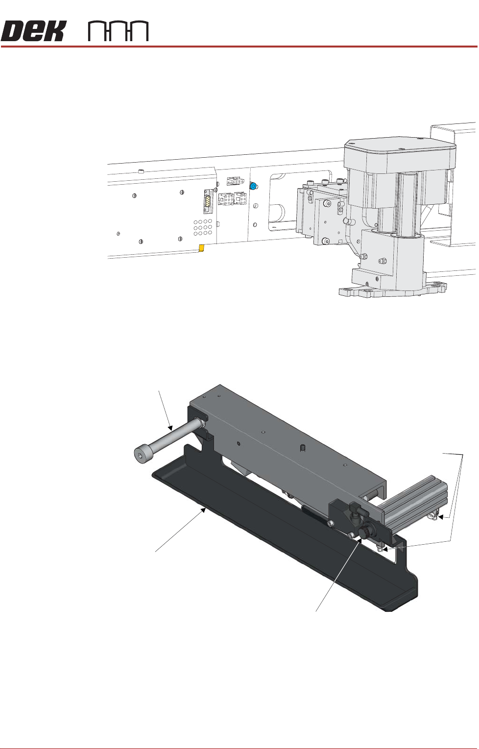
Removing Drip Tray If a screen change mechanism is fitted, carry out the following:
1. Close the speed control valves on the drip tray actuator.
2. Remove the thumbscrew attaching the drip tray to the actuator piston.
3. Slide the drip tray off the bearing on the drip tray guide shaft.
PROFLOW MODULE
REPLACEMENT PROCEDURES
11.14 Technical Reference Manual Chapter Issue 4, Jun 18
Fitting ProFlow 1. Carefully position the ProFlow printhead mechanism so that both locating
dowels locate into the print carriage locating holes. Secure the unit to the
print carriage by means of the four captive screws.
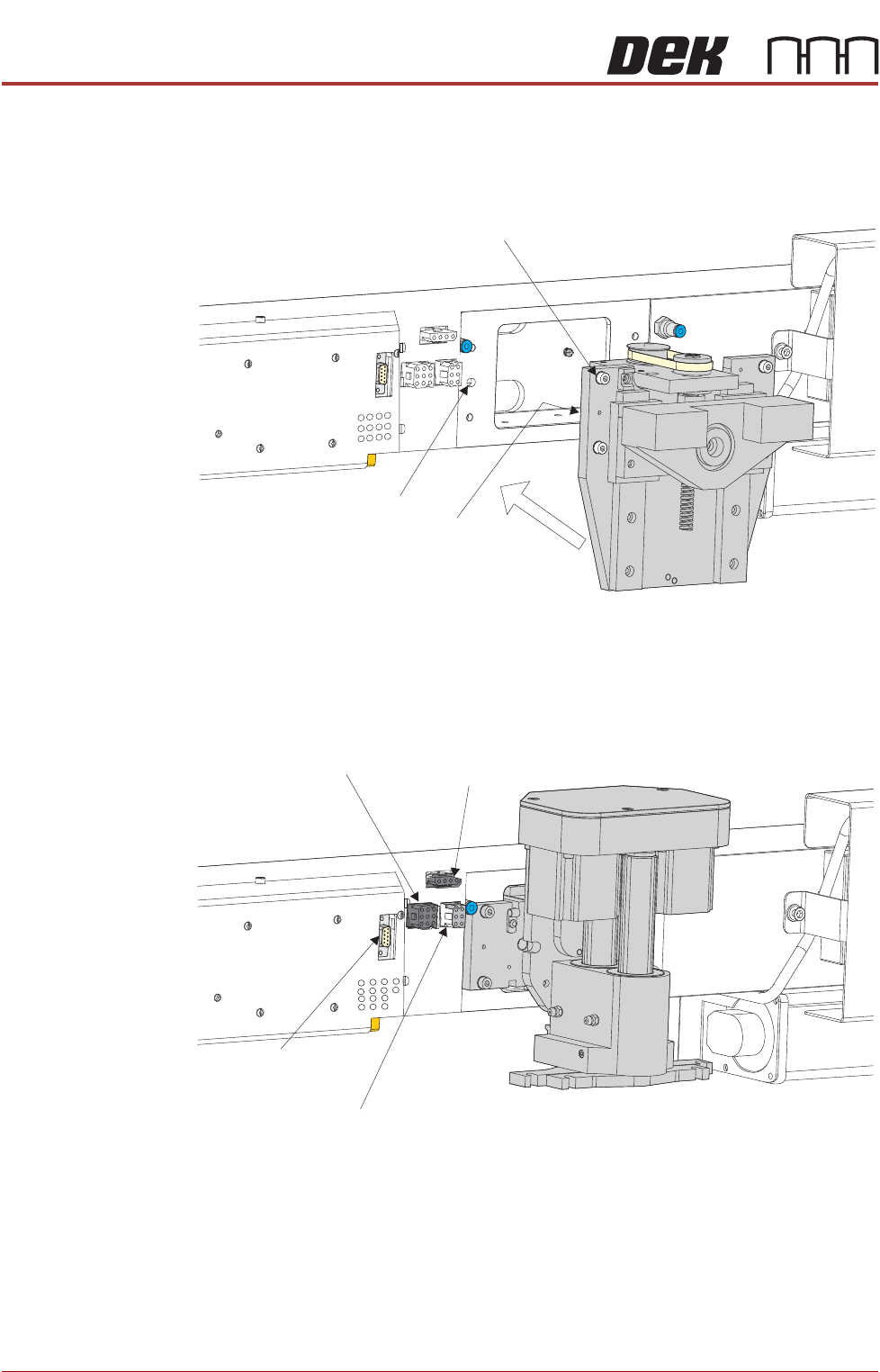
2. Connect the following connectors to the print carriage, left hand side:
• ProFlow Motor
• Home Sensor
! "#
PROFLOW MODULE
REPLACEMENT PROCEDURES
Chapter Issue 4, Jun 18 Technical Reference Manual 11.15
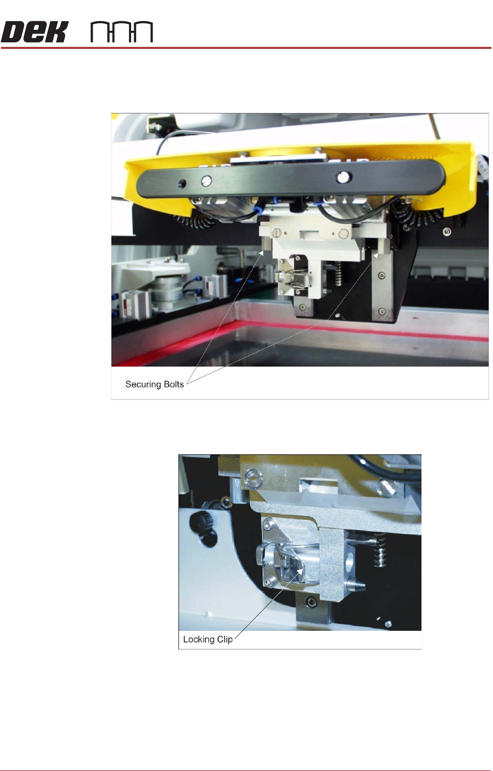
3. Fit the pressure mechanism part of the ProFlow unit to the ProFlow print-
head mechanism bearing block by means of the two securing bolts.
Tighten using a 5mm Allen key.
4. Ensure that the locking clip on the pressure mechanism is pressed over to
the right and clicks into place, as shown in the figure below. This ensures
that the locking clip is in the correct position to secure the transfer head.