Galaxy EX ProFlow Module - 第15页
PR O FLO W MO DU LE REPLACEMENT PRO CEDURES Ch apte r Issue 4, Jun 18 Tech nical Ref erenc e Ma nual 11. 15 3. F i t the p re ssu re me cha nis m pa rt of the Pr oFlo w unit to t he P roFl ow pri nt - hea d m e chan ism …
PROFLOW MODULE
REPLACEMENT PROCEDURES
11.14 Technical Reference Manual Chapter Issue 4, Jun 18
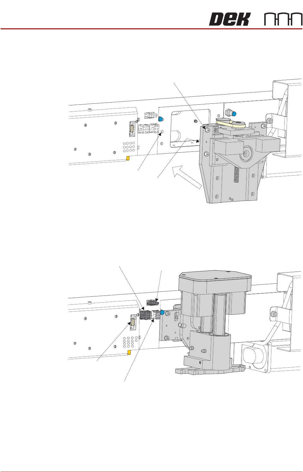
Fitting ProFlow 1. Carefully position the ProFlow printhead mechanism so that both locating
dowels locate into the print carriage locating holes. Secure the unit to the
print carriage by means of the four captive screws.
2. Connect the following connectors to the print carriage, left hand side:
• ProFlow Motor
• Home Sensor
! "#
PROFLOW MODULE
REPLACEMENT PROCEDURES
Chapter Issue 4, Jun 18 Technical Reference Manual 11.15
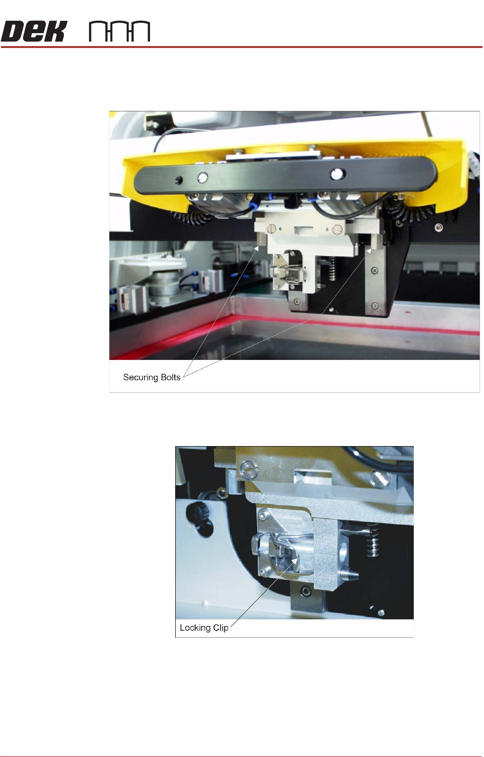
3. Fit the pressure mechanism part of the ProFlow unit to the ProFlow print-
head mechanism bearing block by means of the two securing bolts.
Tighten using a 5mm Allen key.
4. Ensure that the locking clip on the pressure mechanism is pressed over to
the right and clicks into place, as shown in the figure below. This ensures
that the locking clip is in the correct position to secure the transfer head.
PROFLOW MODULE
REPLACEMENT PROCEDURES
11.16 Technical Reference Manual Chapter Issue 4, Jun 18
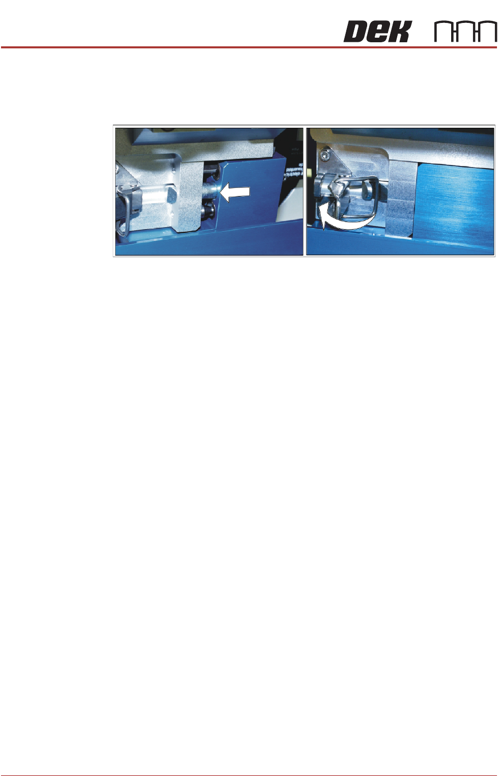
5. Locate and fit the ProFlow transfer head unit to the pressure mechanism
by means of the two locating dowels. Slide the unit onto the pressure
mechanism. Once the unit is slid fully home, it is secured by closing the
locking clip.
6. Connect both curly air lines to the self-seal pneumatic connectors situated
either side of the ProFlow printhead mechanism, figure in Step 2 refers.
7. Connect the ProFlow Paste Level connector to the print carriage, left hand
side, figure in Step 2 refers.
NOTE
a If the squeegee paste dispenser is fitted to the print carriage, before
using ProFlow, ensure that the paste dispenser regulator gauge reads '0'
pressure.
b. This electrical connection informs the machine of ProFlow fitment and
must always be connected whilst the ProFlow unit is fitted otherwise
damage may occur if machine is run.
8. Switch the mains isolator to ON and ensure that the machine recognizes
the ProFlow module fit by displaying ProFlow Uninitialised during the
machine initialisation sequence.
9. Carry out the ProFlow Contact Position Setup in the Calibrations section
later in this chapter.
Drive Belt
Replacement
1. Select Open Cover Commands.
2. Select Carriage To Front.
3. Select Back.
4. Select Shut Down.
5. Select Continue.
6. Switch the mains isolator to OFF.
7. Open the front printhead cover.
8. Disconnect both curly air lines from the self-seal pneumatic connectors sit-
uated either side of the ProFlow printhead mechanism.
9. Disconnect the following connectors from the print carriage, left hand side
(figure in Step 8 of Squeegees to ProFlow section refers):
• ProFlow Motor
• Home Sensor
• ProFlow Paste Level