IPC-TM-650 EN 2022 试验方法--.pdf - 第109页
NIST Certified Standards 5.5 The t est settings used for measuring the metallic foil samples be the s ame as used fo r measuring the NIST- certified standards. 6 Measurement Parameters and Machine setup 6.1 All meas urem…
IPC-TM-650
IPC-TM-650
shall
shall
shall
shall
shall
shall
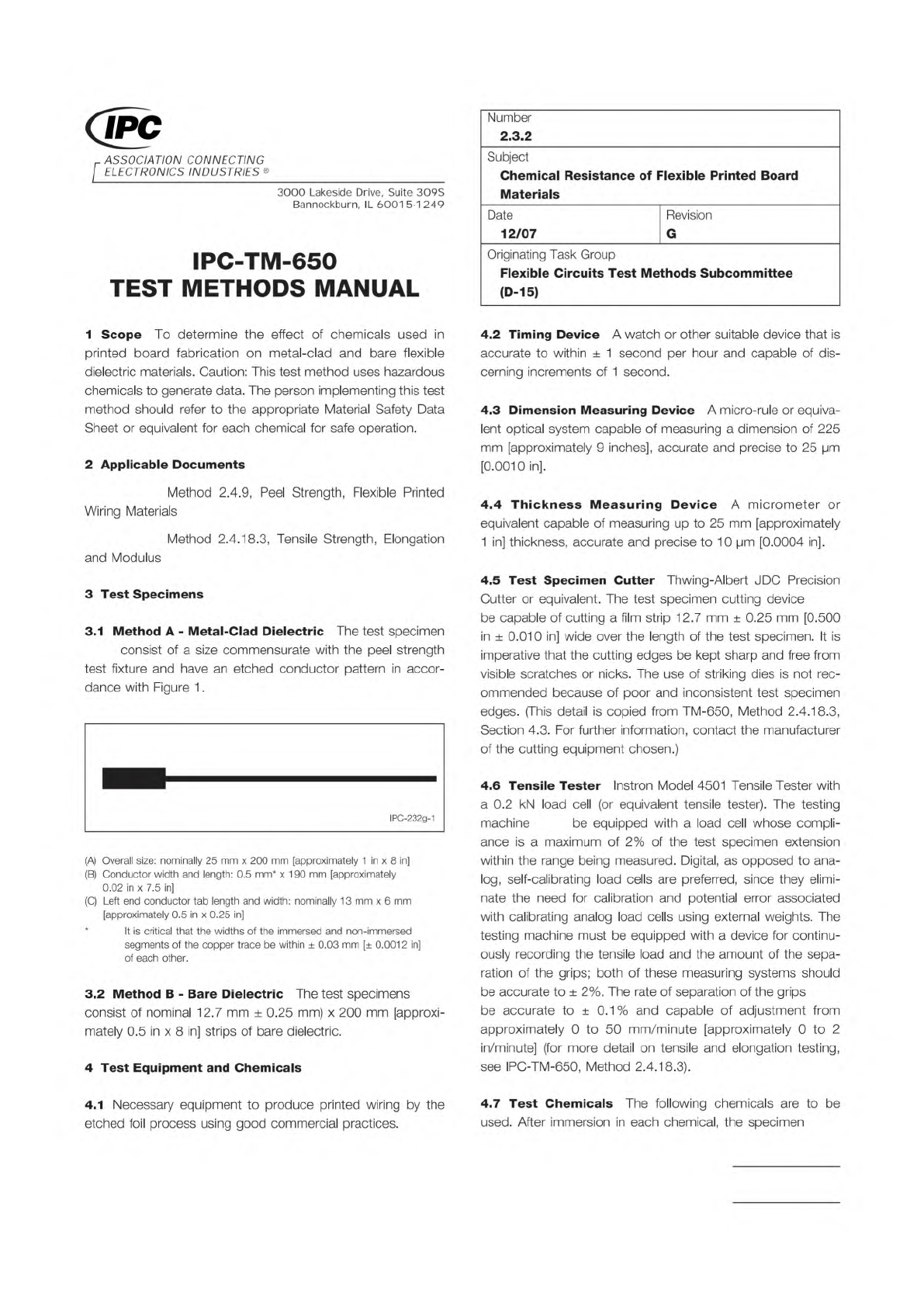
Figure 1 Chemical Resistance Test Pattern
NOTE:
Material in this Test Methods Manual was voluntarily established by Technical Committees of IPC. This material is advisory only
and its use or adaptation is entirely voluntary. IPC disclaims all liability of any kind as to the use, application, or adaptation of this
material. Users are also wholly responsible for protecting themselves against all claims or liabilities for patent infringement.
Equipment referenced is for the convenience of the user and does not imply endorsement by IPC.
Page 1 of 3
r
ASSOCIATION
CONNECTING
/
ELECTRONICS
INDUSTRIES
®
3000
Lakeside
Drive,
Suite
309S
Bannockburn,
IL
6001
5-1
249
IPC-TM-650
TEST
METHODS
MANUAL
1
Scope
To
determine
the
effect
of
chemicals
used
in
printed
board
fabrication
on
metal-clad
and
bare
flexible
dielectric
materials.
Caution:
This
test
method
uses
hazardous
chemicals
to
generate
data.
The
person
implementing
this
test
method
should
refer
to
the
appropriate
Material
Safety
Data
Sheet
or
equivalent
for
each
chemical
for
safe
operation.
2
Applicable
Documents
Method
2.4.9,
Peel
Strength,
Flexible
Printed
Wiring
Materials
Method
2.4.18.3,
Tensile
Strength,
Elongation
and
Modulus
3
Test
Specimens
3.1
Method
A
-
Metal-Clad
Dielectric
The
test
specimen
consist
of
a
size
commensurate
with
the
peel
strength
test
fixture
and
have
an
etched
conductor
pattern
in
accor¬
dance
with
Figure
1
.
IPC-232g-1
(A)
Overall
size:
nominally
25
mm
x
200
mm
[approximately
1
in
x
8
in]
(B)
Conductor
width
and
length:
0.5
mm*
x
190
mm
[approximately
0.02
in
x
7.5
in]
(C)
Left
end
conductor
tab
length
and
width:
nominally
13
mm
x
6
mm
[approximately
0.5
in
x
0.25
in]
*
It
is
critical
that
the
widths
of
the
immersed
and
non-immersed
segments
of
the
copper
trace
be
within
土
0.03
mm
[±
0.0012
in]
of
each
other.
3.2
Method
B
-
Bare
Dielectric
The
test
specimens
consist
of
nominal
12.7
mm
±
0.25
mm)
x
200
mm
[approxi¬
mately
0.5
in
x
8
in]
strips
of
bare
dielectric.
4
Test
Equipment
and
Chemicals
4.1
Necessary
equipment
to
produce
printed
wiring
by
the
etched
foil
process
using
good
commercial
practices.
Number
2.3.2
Subject
Chemical
Resistance
of
Flexible
Printed
Board
Materials
Date
12/07
Revision
G
Originating
Task
Group
Flexible
Circuits
Test
Methods
Subcommittee
(D-15)
4.2
Timing
Device
A
watch
or
other
suitable
device
that
is
accurate
to
within
土
1
second
per
hour
and
capable
of
dis¬
cerning
increments
of
1
second.
4.3
Dimension
Measuring
Device
A
micro-rule
or
equiva¬
lent
optical
system
capable
of
measuring
a
dimension
of
225
mm
[approximately
9
inches],
accurate
and
precise
to
25
pm
[0.0010
in].
4.4
Thickness
Measuring
Device
A
micrometer
or
equivalent
capable
of
measuring
up
to
25
mm
[approximately
1
in]
thickness,
accurate
and
precise
to
10
pm
[0.0004
in].
4.5
Test
Specimen
Cutter
Thwing-Albert
J
DC
Precision
Cutter
or
equivalent.
The
test
specimen
cutting
device
be
capable
of
cutting
a
film
strip
12.7
mm
±
0.25
mm
[0.500
in
±
0.01
0
in]
wide
over
the
length
of
the
test
specimen.
It
is
imperative
that
the
cutting
edges
be
kept
sharp
and
free
from
visible
scratches
or
nicks.
The
use
of
striking
dies
is
not
rec¬
ommended
because
of
poor
and
inconsistent
test
specimen
edges.
(This
detail
is
copied
from
TM-650,
Method
2.4.18.3,
Section
4.3.
For
further
information,
contact
the
manufacturer
of
the
cutting
equipment
chosen.)
4.6
Tensile
Tester
Instron
Model
4501
Tensile
Tester
with
a
0.2
kN
load
cell
(or
equivalent
tensile
tester).
The
testing
machine
be
equipped
with
a
load
cell
whose
compli¬
ance
is
a
maximum
of
2%
of
the
test
specimen
extension
within
the
range
being
measured.
Digital,
as
opposed
to
ana¬
log,
self-calibrating
load
cells
are
preferred,
since
they
elimi¬
nate
the
need
for
calibration
and
potential
error
associated
with
calibrating
analog
load
cells
using
external
weights.
The
testing
machine
must
be
equipped
with
a
device
for
continu¬
ously
recording
the
tensile
load
and
the
amount
of
the
sepa¬
ration
of
the
grips;
both
of
these
measuring
systems
should
be
accurate
to
土
2%.
The
rate
of
separation
of
the
grips
be
accurate
to
±
0.1%
and
capable
of
adjustment
from
approximately
0
to
50
mm/m
inute
[approximately
0
to
2
in/minute]
(for
more
detail
on
tensile
and
elongation
testing,
see
IPC-TM-650,
Method
2.4.18.3).
4.7
Test
Chemicals
The
following
chemicals
are
to
be
used.
After
immersion
in
each
chemical,
the
specimen
NIST Certified Standards
5.5
The test settings used for measuring the metallic foil
samples
be the same as used for measuring the NIST-
certified standards.
6 Measurement Parameters and Machine setup
6.1
All measurements will be done using a saved set-up and
measurement parameters (commonly termed ‘‘a template’’) to
insure that all measurements are done using the exact same
test method. Programs and procedures for each piece of spe-
cific equipment
be saved and distributed to colleagues
across the country so all facilities are taking the exact same
measurements using the exact same test procedure. For
example, procedures for laser or white light techniques will be
different.
6.2
The equipment manufacturer should be consulted to
define the specific measurement machine template needed to
assure compliance with this measurement procedure.
6.3
The specifics of the surface measurements are listed
below.
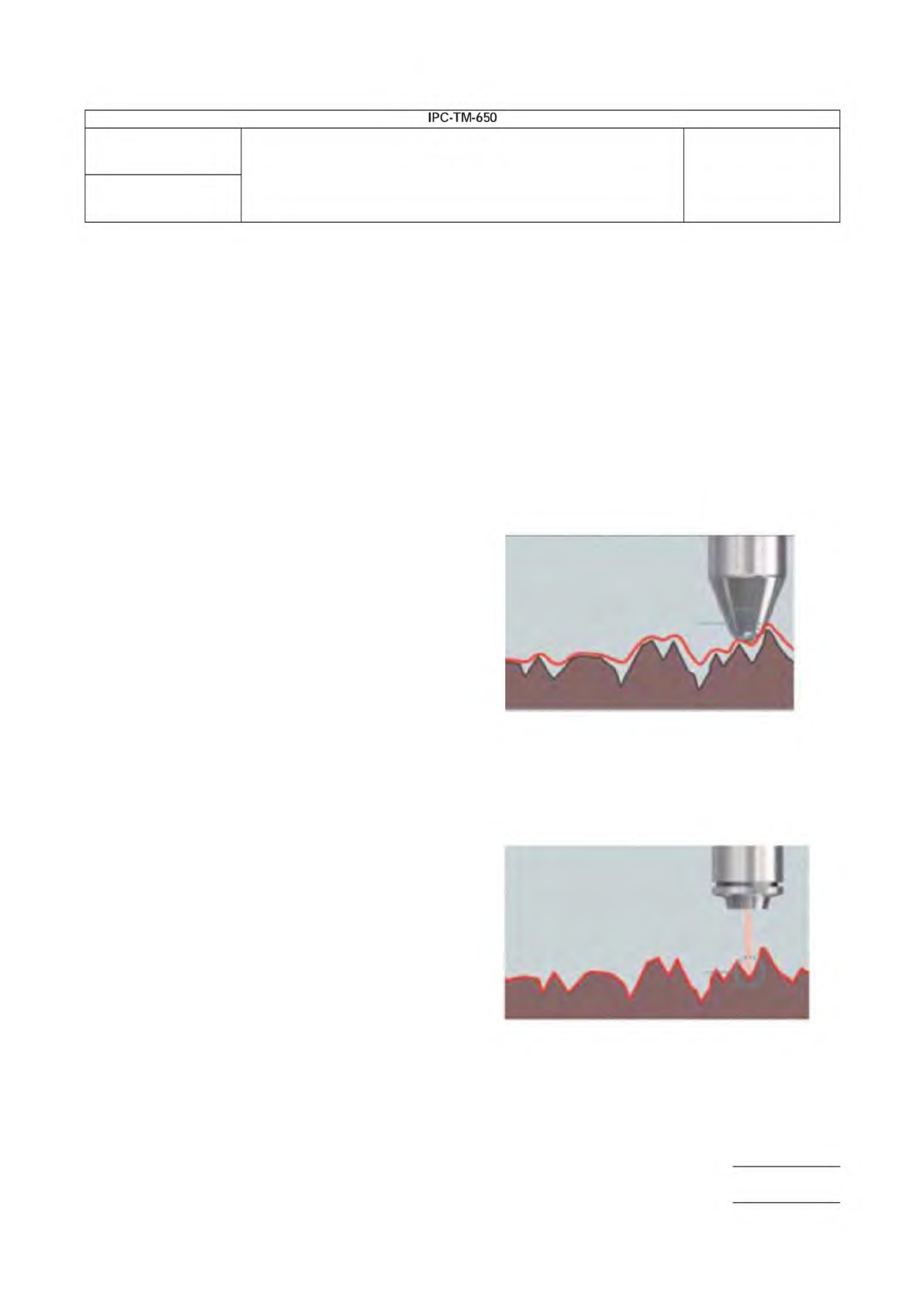
Primary Measurement Values: Sa, Sq, Sz
• is defined as the average absolute value height in refer-
ence to the mean plane.
•
is defined as the root mean square (RMS) height in ref-
erence to the mean plane.
•
is defined as the absolute vertical distance between the
highest peak and deepest valley.
7 Measurement Results
7.1
The values for Sq, Sa and Sz will be used to quantify the
overall surface texture/topography of various metallic foils and
will be reported. These values were chosen as they provide
the most up-to-date surface measurement capabilities using a
noncontact 3-D surface measurement tool.
Height 9 mm
x 200 µm (width); centered on the xy axis
Center point of Measurement spot and Standard
Grain direction of the standard is across the width
Measurement standard minimum size 1000 µm (height)
Width 3 mm
Number
2.2.22
Subject
Noncontact Metallic Foil Surface Topography/Texture
Date
5/20
Revision
Page 2 of 5
IPC-TM-650
shall
Sa
Sq
Sz
shall
APPENDIX A
A.1 Surface Roughness Standard: ISO 25178-2
This
ISO standard is grouped into six different categories and each
of these values are reported in the ‘‘Height Parameters’’ sec-
tion. The conventional ISO 4287:2001 was defined for
contact-type tools and does not provide as much detail as the
ISO 25178-2 standard.
A.1.1 Filter Type: Gaussian Filter
This is used for deter-
mining the mean plane in surface metrology. This is defined by
ISO 1661 and is applied to areal surface roughness measure-
ments.
A.1.2 Surface Type: S-L Surface
Defines a surface
obtained after using the L-Filter. This filter removes undula-
tions and other surface variations, allowing for the measure-
ment of only the surface topography/texture without
geometric influence.
A.1.3 S-Filter
This is chosen based on the specifications of
the objective lens used to capture the data. This filter elimi-
nates the smallest scale elements from the surface, shortest
wavelength filter. S-filter should be no smaller than the spot
size multiplied by 2.5.
A.1.4 F-Operation: Plane Correction
Chosen based on
the planar features of the surface of metallic foils.
A.1.5 L-Filter
This is chosen based on the area of the total
minimum scanned section (1000 µm X 200 µm). This filter
eliminates the largest scale elements from the surface, longest
wavelength filter. L-filter should be no larger than entire scan
length divided by 5.
A.2 Filter Selection and Filter Explanations
A.2.1
The main differentiator between the ISO 4287 and ISO
25178 is how the acquired data set is processed to maximize
the accuracy of the calculated roughness values. The old
standard used terms like λs and λc to account for the stylus
tip size and total evaluation length, which are specific towards
contact profilers. The newest standard uses filters to account
for similar features of noncontact 3-D profilers: the objective
lens used for analysis and total XYZ coverage area. Listed
below is additional detail to describe how the S-filter,
F-operation and L-filter are defined.
S-Filter:
• Commonly known as a low-pass filter.
• This filter is equivalent to λs for line roughness defined by
ISO 4287.
• Eliminates noisy data that varies based on the size of beam
spot. This will vary based on the objective lens chosen for
the analysis. (see below for explanation)
Low mag lens, larger beam spot, high
S-filter value
High mag lens, smaller beam spot, low
S-filter value
Vs.
Number
2.2.22
Subject
Noncontact Metallic Foil Surface Topography/Texture
Date
5/20
Revision
Page 3 of 5
IPC-TM-650