IPC-TM-650 EN 2022 试验方法--.pdf - 第115页
Chemical Con cent ration T e mperature Chemical Con centration T emperature The Institute for Int erconnecting and Packaging E lectronic Circuits 2215 S anders Road • Northbrook, IL 60062-6135 Material in this T est M et…
IPC-TM-650
Number
Subject Date
Revision
Page 2 of 2
4/73
2.3.1
Chemical
Processing,
Suitable
Processing
Material
5.3.4
Drill
1.5
mm
holes
in
the
pads
of
the
3
mm
lines
with
good
fabricating
practice.
5.3.5
Remove
the
developed
KPR
by
rubbing
the
pattern
lightly
with
cold
trichlorethylene
liquid.
Rinse
in
water.
Scrub
the
specimens
with
FFF
pumice
and
water
with
a
strong
bristle
brush.
5.3.6
Plate
(this
is
simulated
plating)
per
MIL-P-1
3949.
5.3.7
Deoxidize
by
dipping
in
10%
hydrochloric
acid
for
two
minutes
and
wash
in
running
water
for
five
minutes.
Dry
30
minutes,
minimum,
at
105℃
to1
10℃.
5.3.8
Coat
the
etched
copper
surface
with
white
petrola¬
tum.
Specimens
shall
be
immersed
horizontally
in
solder
6.5
mm
below
the
surface
for
20
土
1
seconds
at
260℃
+5/-0℃
measured
25
mm
below
the
surface.
5.3.9
Remove
the
petrolatum
from
the
surface
of
the
speci¬
men
with
a
two
minute
scrub
in
cold
trichlorethylene,
followed
by
a
one
minute
rinse
in
hot
trichlorethylene.
5.3.10
Inspect
the
surface
for
weave
exposure,
measling,
crazing,
resin
loss,
delamination,
and
blistering.
5.3.11
Test
four
1
mm
lines
on
the
specimen
for
peel
strength
per
MIL-P-13949,
reporting
the
average
value
for
the
four
lines.
Chemical Concentration Temperature
Chemical Concentration Temperature
The Institute for Interconnecting and Packaging Electronic Circuits
2215 Sanders Road • Northbrook, IL 60062-6135
Material in this Test Methods Manual was voluntarily established by Technical Committees of the IPC. This material is advisory only
and its use or adaptation is entirely voluntary. IPC disclaims all liability of any kind as to the use, application, or adaptation of this
material. Users are also wholly responsible for protecting themselves against all claims or liabilities for patent infringement.
Equipment referenced is for the convenience of the user and does not imply endorsement by the IPC.
Page 1 of 1
IPC-TM-650
TEST
METHODS
MANUAL
1
.0
Scope
This
method
evaluates
the
chemical
cleanability
of
metal-clad
laminate
surfaces
of
oxidation
and
anti-oxidation
protective
coatings.
2
.0
Applicable
Document
None.
3
.0
Test
Specimen
The
size
of
the
test
specimen
shall
be
determined
by
the
post
etching
tests
to
be
performed.
4
.0
Apparatus
4.1
Standard
conveyorized
spray
cleaning
modules
or
suit¬
able
laboratory
equipment.
4.2
Personal
safety
equipment
needed
to
perform
this
test
are
as
follows:
rubber
or
polyethylene
gloves,
plastic
or
coated
apron
and
safety
goggles.
4.3
Chemicals
4.3.1
Method
A
~
Sodium
Persulfate
Cleaner/
Degreaser
Sodium
Persulfate
Per
manufacturer's
recommended
limits
1.5
Ibs/gal
(土
0.5
Ib/gal)
As
recommended
100°±5°F
(38°
±
3
℃)
4.3.2
Method
B
一
Ammonium
Persulfate
Cleaner/
Degreaser
Ammonium
Persulfate
Tech
Grade
Per
manufacturer's
recommended
limits
2.0
Ibs/gal
(±
0.5
Ib/gal)
As
recommended
100°F
Max
Number
2.3.1.
1
Subject
Chemical
Cleaning
of
Metal-Clad
Laminate
Date
Revision
5/86
B
Originating
Task
Group
N/A
5.0
Procedure
5.1
Specimen
Preparation
Shear
the
material
to
the
required
specimen
size
and
remove
the
rough
edges
from
the
specimen
by
sanding
or
other
suitable
means.
5.2
Cleaning
5.2.1
Conveyorized
Spray
Cleaning
Process
the
speci¬
men
through
the
conveyorized
modules
at
a
speed
which
will
permit
30
±
5
seconds
of
exposure
to
the
micro
etching
solu¬
tion.
Rinse
specimens
with
deionized
water
for
1-2
minutes
after
micro
etching.
5.2.2
Laboratory
Cleaning
Place
the
specimen
in
a
cleaner/degreaser
solution
and
gently
agitate
for
30
±
5
sec¬
onds.
Remove
the
specimen
and
flush
with
tap
water.
Next
place
the
specimen
in
a
micro
etch
solution
for
30
±
5
sec¬
onds
and
vigorously
agitate.
Remove
the
specimen
and
flush
with
deionized
water
for
1
-2
minutes.
5.3
Surface
Evaluation
The
metal
cladding
on
the
test
specimen
shall
be
cleaned
to
a
uniform
matte
finish.
Deionized
or
distilled
water
poured
on
the
metal
surface
does
not
bead
or
form
puddles.
6.0
Notes
6.1
Sodium
persulfate
solution
shall
be
replaced
if
the
cop¬
per
concentration
exceeds
3.0
oz/gal
(22.5
gal).
6.2
Solution
spray
from
nozzles
should
be
checked
for
uni¬
formity
across
the
specimen.
IPC-TM-650
IPC-TM-650
shall
shall
shall
shall
shall
shall
Figure 1 Chemical Resistance Test Pattern
NOTE:
Material in this Test Methods Manual was voluntarily established by Technical Committees of IPC. This material is advisory only
and its use or adaptation is entirely voluntary. IPC disclaims all liability of any kind as to the use, application, or adaptation of this
material. Users are also wholly responsible for protecting themselves against all claims or liabilities for patent infringement.
Equipment referenced is for the convenience of the user and does not imply endorsement by IPC.
Page 1 of 3
r
ASSOCIATION
CONNECTING
/
ELECTRONICS
INDUSTRIES
®
3000
Lakeside
Drive,
Suite
309S
Bannockburn,
IL
6001
5-1
249
IPC-TM-650
TEST
METHODS
MANUAL
1
Scope
To
determine
the
effect
of
chemicals
used
in
printed
board
fabrication
on
metal-clad
and
bare
flexible
dielectric
materials.
Caution:
This
test
method
uses
hazardous
chemicals
to
generate
data.
The
person
implementing
this
test
method
should
refer
to
the
appropriate
Material
Safety
Data
Sheet
or
equivalent
for
each
chemical
for
safe
operation.
2
Applicable
Documents
Method
2.4.9,
Peel
Strength,
Flexible
Printed
Wiring
Materials
Method
2.4.18.3,
Tensile
Strength,
Elongation
and
Modulus
3
Test
Specimens
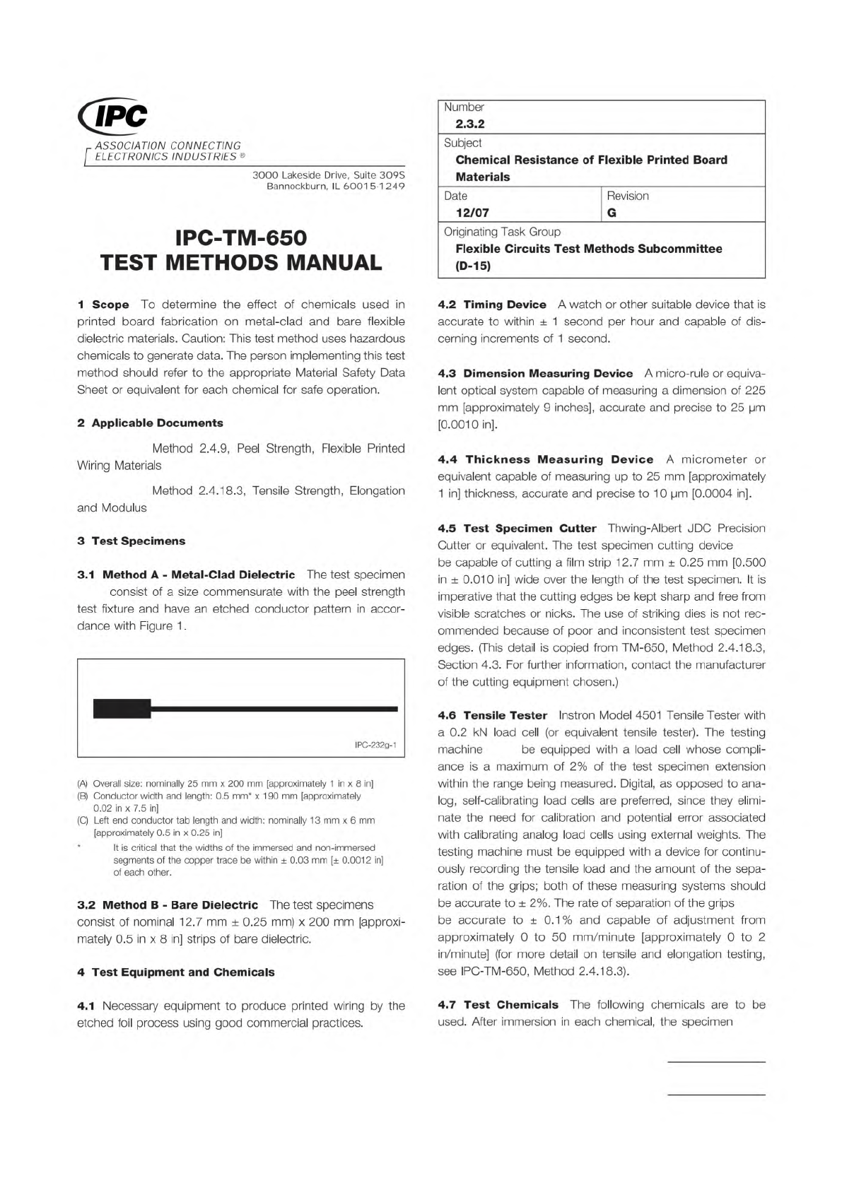
3.1
Method
A
-
Metal-Clad
Dielectric
The
test
specimen
consist
of
a
size
commensurate
with
the
peel
strength
test
fixture
and
have
an
etched
conductor
pattern
in
accor¬
dance
with
Figure
1
.
IPC-232g-1
(A)
Overall
size:
nominally
25
mm
x
200
mm
[approximately
1
in
x
8
in]
(B)
Conductor
width
and
length:
0.5
mm*
x
190
mm
[approximately
0.02
in
x
7.5
in]
(C)
Left
end
conductor
tab
length
and
width:
nominally
13
mm
x
6
mm
[approximately
0.5
in
x
0.25
in]
*
It
is
critical
that
the
widths
of
the
immersed
and
non-immersed
segments
of
the
copper
trace
be
within
土
0.03
mm
[±
0.0012
in]
of
each
other.
3.2
Method
B
-
Bare
Dielectric
The
test
specimens
consist
of
nominal
12.7
mm
±
0.25
mm)
x
200
mm
[approxi¬
mately
0.5
in
x
8
in]
strips
of
bare
dielectric.
4
Test
Equipment
and
Chemicals
4.1
Necessary
equipment
to
produce
printed
wiring
by
the
etched
foil
process
using
good
commercial
practices.
Number
2.3.2
Subject
Chemical
Resistance
of
Flexible
Printed
Board
Materials
Date
12/07
Revision
G
Originating
Task
Group
Flexible
Circuits
Test
Methods
Subcommittee
(D-15)
4.2
Timing
Device
A
watch
or
other
suitable
device
that
is
accurate
to
within
土
1
second
per
hour
and
capable
of
dis¬
cerning
increments
of
1
second.
4.3
Dimension
Measuring
Device
A
micro-rule
or
equiva¬
lent
optical
system
capable
of
measuring
a
dimension
of
225
mm
[approximately
9
inches],
accurate
and
precise
to
25
pm
[0.0010
in].
4.4
Thickness
Measuring
Device
A
micrometer
or
equivalent
capable
of
measuring
up
to
25
mm
[approximately
1
in]
thickness,
accurate
and
precise
to
10
pm
[0.0004
in].
4.5
Test
Specimen
Cutter
Thwing-Albert
J
DC
Precision
Cutter
or
equivalent.
The
test
specimen
cutting
device
be
capable
of
cutting
a
film
strip
12.7
mm
±
0.25
mm
[0.500
in
±
0.01
0
in]
wide
over
the
length
of
the
test
specimen.
It
is
imperative
that
the
cutting
edges
be
kept
sharp
and
free
from
visible
scratches
or
nicks.
The
use
of
striking
dies
is
not
rec¬
ommended
because
of
poor
and
inconsistent
test
specimen
edges.
(This
detail
is
copied
from
TM-650,
Method
2.4.18.3,
Section
4.3.
For
further
information,
contact
the
manufacturer
of
the
cutting
equipment
chosen.)
4.6
Tensile
Tester
Instron
Model
4501
Tensile
Tester
with
a
0.2
kN
load
cell
(or
equivalent
tensile
tester).
The
testing
machine
be
equipped
with
a
load
cell
whose
compli¬
ance
is
a
maximum
of
2%
of
the
test
specimen
extension
within
the
range
being
measured.
Digital,
as
opposed
to
ana¬
log,
self-calibrating
load
cells
are
preferred,
since
they
elimi¬
nate
the
need
for
calibration
and
potential
error
associated
with
calibrating
analog
load
cells
using
external
weights.
The
testing
machine
must
be
equipped
with
a
device
for
continu¬
ously
recording
the
tensile
load
and
the
amount
of
the
sepa¬
ration
of
the
grips;
both
of
these
measuring
systems
should
be
accurate
to
土
2%.
The
rate
of
separation
of
the
grips
be
accurate
to
±
0.1%
and
capable
of
adjustment
from
approximately
0
to
50
mm/m
inute
[approximately
0
to
2
in/minute]
(for
more
detail
on
tensile
and
elongation
testing,
see
IPC-TM-650,
Method
2.4.18.3).
4.7
Test
Chemicals
The
following
chemicals
are
to
be
used.
After
immersion
in
each
chemical,
the
specimen