IPC-TM-650 EN 2022 试验方法--.pdf - 第141页
Figure 1 IPC-TM-650 Number Subject Date Revision Page 3 of 3 2.3.17.2 Resin Flow of “No Flow" Prepreg 8/97 B IPC-23172-fig1
IPC-TM-650
Number
Subject Date
Revision
Page 2 of 3
8/97
2.3.17.2
Resin
Flow
of
uNo
Flow”
Prepreg
B
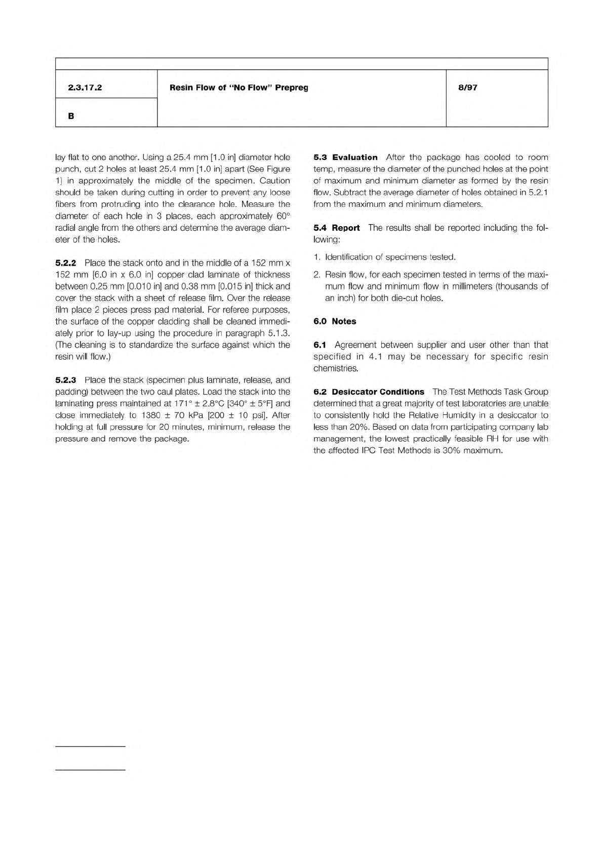
lay
flat
to
one
another.
Using
a
25.4
mm
[1.0
in]
diameter
hole
punch,
cut
2
holes
at
least
25.4
mm
[1.0
in]
apart
(See
Figure
1)
in
approximately
the
middle
of
the
specimen.
Caution
should
be
taken
during
cutting
in
order
to
prevent
any
loose
fibers
from
protruding
into
the
clearance
hole.
Measure
the
diameter
of
each
hole
in
3
places,
each
approximately
60°
radial
angle
from
the
others
and
determine
the
average
diam¬
eter
of
the
holes.
5.2.2
Place
the
stack
onto
and
in
the
middle
of
a
1
52
mm
x
152
mm
[6.0
in
x
6.0
in]
copper
clad
laminate
of
thickness
between
0.25
mm
[0.010
in]
and
0.38
mm
[0.015
in]
thick
and
cover
the
stack
with
a
sheet
of
release
film.
Over
the
release
film
place
2
pieces
press
pad
material.
For
referee
purposes,
the
surface
of
the
copper
cladding
shall
be
cleaned
immedi¬
ately
prior
to
lay-up
using
the
procedure
in
paragraph
5.1
.3.
(The
cleaning
is
to
standardize
the
surface
against
which
the
resin
will
flow.)
5.2.3
Place
the
stack
(specimen
plus
laminate,
release,
and
padding)
between
the
two
caul
plates.
Load
the
stack
into
the
laminating
press
maintained
at
1
7
1
°
±
2.8℃
[340°
±
5°F]
and
close
immediately
to
1380
±
70
kPa
[200
±
10
psi].
After
holding
at
full
pressure
for
20
minutes,
minimum,
release
the
pressure
and
remove
the
package.
5.3
Evaluation
After
the
package
has
cooled
to
room
temp,
measure
the
diameter
of
the
punched
holes
at
the
point
of
maximum
and
minimum
diameter
as
formed
by
the
resin
flow.
Subtract
the
average
diameter
of
holes
obtained
in
5.2.1
from
the
maximum
and
minimum
diameters.
5.4
Report
The
results
shall
be
reported
including
the
fol¬
lowing:
1.
Identification
of
specimens
tested.
2.
Resin
flow,
for
each
specimen
tested
in
terms
of
the
maxi¬
mum
flow
and
minimum
flow
in
millimeters
(thousands
of
an
inch)
for
both
die-cut
holes.
6.0
Notes
6.1
Agreement
between
supplier
and
user
other
than
that
specified
in
4.1
may
be
necessary
for
specific
resin
chemistries.
6.2
Desiccator
Conditions
The
Test
Methods
Task
Group
determined
that
a
great
majority
of
test
laboratories
are
unable
to
consistently
hold
the
Relative
Humidity
in
a
desiccator
to
less
than
20%.
Based
on
data
from
participating
company
lab
management,
the
lowest
practically
feasible
RH
for
use
with
the
affected
IPC
Test
Methods
is
30%
maximum.
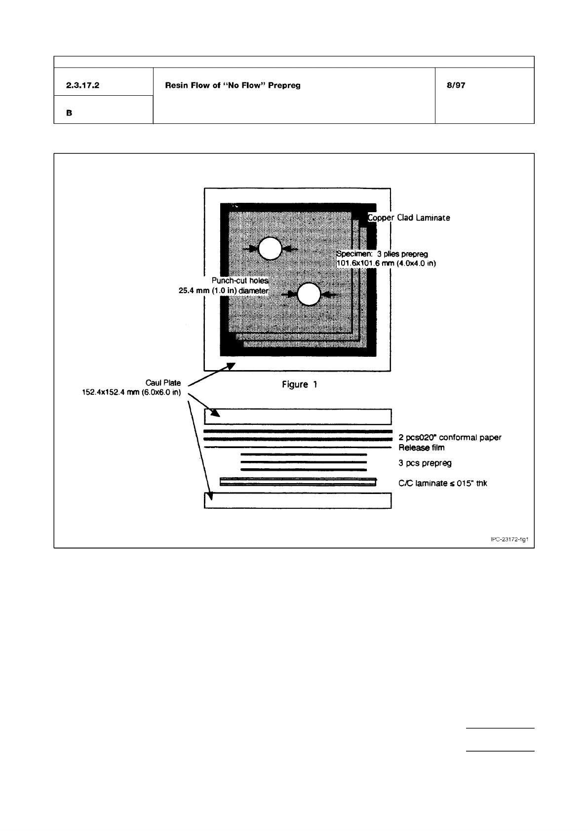
Figure 1
IPC-TM-650
Number
Subject Date
Revision
Page 3 of 3
2.3.17.2
Resin
Flow
of
“No
Flow"
Prepreg
8/97
B
IPC-23172-fig1
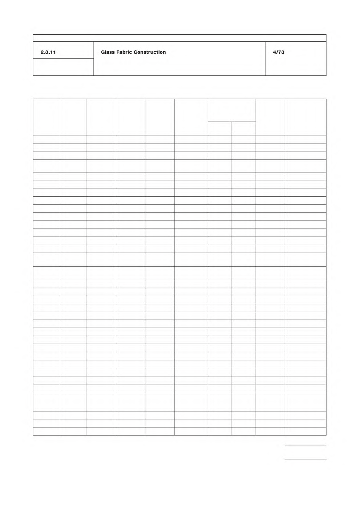
Table 1
Cloth
No.
Nominal
Width
Inches
Thickness
Inch
Weight
Per
Square
Yard
Ounces
Yarn,
Warp,
and Fill Construction
Minimum
Breaking
Strength Per
Inch of Width
Yards per
Standard
Roll Type of Weave
Warp
Pounds
Fill
Pounds
106 38 0.0015 0.85 900-1/0 56x56 46 52 250 ± 25 Plain
108 38 0.0020 1.43 900-1/2 60x47 70 40 250 ± 25 Plain
112 38 0.0030 2.09 450-1/2 40x39 82 80 250 ± 25 Plain
113 38 0.0030 2.46 450-1/2
900-1/2
60x64 123 60 250 ± 25 Plain
116 38 0.0040 3.16 450-1/2 60x58 123 120 250 ± 25 Plain
119 38 0.0040 2.80 450-1/2 54x50 110 100 250 ± 25 Plain
120 38 0.0040 3.16 450-1/2 60x58 125 120 250 ± 25 4-harness satin
126-150 38 0.0060 5.50 150-1/2 34x32 225 195 250 ± 25 Plain
126 38 0.0065 5.37 450-3/2 34x32 205 185 250 ± 25 Plain
127 38 0.0070 6.00 450-3/2 42x32 225 185 250 ± 25 Plain
128 38 0.0070 6.00 225-1/3 42x32 250 200 250 ± 25 Plain
128-150 38 0.0067 6.00 150-1/2 42x32 250 200 250 ± 25 Plain
140 38 0.0100 8.70 450-4/3 32x21 400 290 125 ± 25 Plain
141 38 0.0100 8.70 225-2/3 32x21 400 290 125 ± 25 Plain
143 38 0.0090 8.90 225-3/2
450-1/2
49x30 611 56 125 ± 25 4-harness satin
143-150 38 0.0086 9.40 150-2/2
450-1/2
49x30 660 70 125 ± 25 4-harness satin
148 38 0.0120 10.10 450-3/5 30x19 450 360 125 ± 25 Plain
149 38 0.0120 10.80 225-2/4 30x19 450 360 125 ± 25 Plain
161 38 0.0150 12.20 450-4/5 28x16 550 450 125 ± 25 Plain
162 38 0.0150 12.20 225-2/5 28x16 450 350 125 ± 25 Plain
164 38 0.0150 12.60 225-4/3 20x18 500 450 125 ± 25 Plain
164-150 38 0.0140 13.00 150-4/2 20x18 500 450 125 ± 25 Plain
181 38 0.0085 8.90 225-1/3 57x54 340 330 125 ± 25 8-harness satin
181-150 38 0.0080 9.50 150-1/2 56x54 350 325 125 ± 25 Plain
182 38 0.0130 12.40 225-2/2 60x56 440 400 125 ± 25 8-harness satin
182-150 38 0.0134 12.65 150-1/3 60x56 440 400 125 ± 25 Plain
183 38 0.0180 16.75 225-3/2 54x48 650 620 75 ± 15 8-harness satin
184 38 0.0270 25.90 225-4/3 42x36 950 800 50 ± 10 8-harness satin
184-150 38 0.0246 24.16 150-4/2 44x35 950 800 50 ± 10
573-150 38 0.0110 8.00 150-3/2 16x16 335 316 125 ± 25 Plain
1000-150 38
and
44
0.0130 9.66 150-4/2 16x14 450 410 125 ± 25 Plain
1044-150 38 0.0220 19.20 ...... 16x14 450 410 125 ± 25 Plain
1523-150 38 0.0140 11.70 150-3/2 28x20 525 400 125 ± 25 Plain
1527-150 38 0.0150 12.90 150-3/3 17x17 535 485 125 ± 25 Plain
IPC-TM-650
Number
Subject Date
Revision
Page 3 of 3
2.3.11
Glass
Fabric
Construction
4/73