IPC-TM-650 EN 2022 试验方法--.pdf - 第165页
The Institute for Int erconnecting and Packaging E lectronic Circuits 2215 S anders Road • Northbrook, IL 60062-6135 Material in this T est M ethods Manual was vol untaril y establis hed by T echni cal Committees of the …
IPC-TM-650
Number
Subject Date
Revision
Page 3 of 3
2.3.19
Volatile
Content
of
Prepreg
12/94
C
6.0
Notes
6.1
Moisture
Content
6.1.1
Exclusion
of
Moisture
Content
Desiccation
of
the
specimens
is
performed
for
the
following
reasons.
6.1.
1.1
This
test
method
is
based
on
the
understanding
that
"Volatile
Content"
refers
to
organic
solvents
and
other
ingre¬
dients
of
the
prepreg
that
may
remain
in
the
material
after
curing.
Water
or
moisture
content
is
not
considered
as
a
"Volatile”
for
purposes
of
this
test,
and
therefore
desiccation
is
a
fundamental
step
to
exclude
H20
from
the
data.
It
is
not
possible
to
remove
all
H20
from
material
that
is
hygroscopic,
but
the
most
significant
content
is
removed.
6.1.
1.2
This
method
has
a
high
intrinsic
variability
potential,
and
since
moisture
content
is
extremely
variable
and
depen¬
dent
on
the
storage
environment,
meaningful
data
is
best
achieved
by
removing
the
moisture.
6.1.2
Moisture
Content
Determination
This
method
can
be
performed
in
an
alternative
manner,
in
which
the
specimen
is
weighed
before
it
is
desiccated.
The
difference
between
the
"As
Is
Weight”
and
the
"Weight
After
Desiccation"
(but
before
oven
drying)
is
the
moisture
content.
6.2
Alternate
Specimen
Holder
Method
B
has
been
designed
to
minimize
the
problem
of
specimens
flopping
around
in
the
air
circulating
oven.
6.3
Desiccator
Conditions
The
Test
Methods
Task
Group
determined
that
a
great
majority
of
test
laboratories
are
unable
to
consistently
hold
the
Relative
Humidity
in
a
desiccator
to
less
than
20%.
Based
on
data
from
participating
company
lab
management,
the
lowest
practically
feasible
RH
for
use
with
the
affected
IPG
Test
Methods
is
30%
maximum.
The Institute for Interconnecting and Packaging Electronic Circuits
2215 Sanders Road • Northbrook, IL 60062-6135
Material in this Test Methods Manual was voluntarily established by Technical Committees of the IPC. This material is advisory only
and its use or adaptation is entirely voluntary. IPC disclaims all liability of any kind as to the use, application, or adaptation of this
material. Users are also wholly responsible for protecting themselves against all claims or liabilities for patent infringement.
Equipment referenced is for the convenience of the user and does not imply endorsement by the IPC.
Page 1 of 3
IPC-TM-650
TEST
METHODS
MANUAL
1
.0
Scope
1.1
The
Hull
Cell
is
a
miniature
plating
unit
designed
to
pro¬
duce
cathode
deposits
on
a
panel
that
correlates
the
charac¬
teristics
of
the
plating
unit
being
evaluated.
Interpretation
of
the
“as
plated"
cathode
panel
give
rapid
information
about
brightness
levels,
irregular
plate
deposits,
uniformity
of
depos¬
its,
coverage,
throwing
power,
impurities,
and
plating
bath
chemistry.
1
.2
Theory:
Within
the
parameters
of
recommended
operat¬
ing
characteristics
of
a
particular
plating
solution,
the
HULL
CELL
will
duplicate
what
is
actually
occurring
in
the
plating
unit
proper.
Correlation
of
the
"as
plated”
panel
and
the
HULL
CELL
SCALE
allows
rapid,
nondestructive
testing
of
plating
solu¬
tions
for
research,
preventative
maintenance,
troubleshooting,
and
quality
control.
2
.0
Applicable
Documents
R.
O.
Technical
Bulletin
No.
404
The
Hull
Cell,
by
Sedusky
and
Mohler
3
.0
Test
Specimen
3.1
Description
of
Specimen
A
representative
sample
from
the
plating
unit
to
be
evaluated
is
withdrawn
and
should
be
a
composite
sampling
from
various
areas
in
the
plating
tank
and
from
various
depths
within
these
areas.
3.2
Specimen
Preparation
The
representative
sample
should
be
analyzed
chemically
for
those
critical
components
recommended
by
the
supplier
of
the
plating
bath.
Correlation
of
Hull
Cell
panels
without
the
information
on
the
bath
chem¬
istry
can
be
very
misleading.
3.3
Operating
Conditions
Particular
attention
shall
be
given
to
the
physical
conditions
of
the
plating
unit
at
the
time
of
sampling
and
these
operating
conditions
should
be
dupli¬
cated
during
Hull
Cell
testing.
If
this
is
not
done,
interpretation
will
be
meaningless.
Example:
temperature,
cathode
agitation,
air
agitation.
Number
2.3.21
Subject
Plating
Quality
Hull
Cell
1
Method
Date
Revision
8/97
A
Originating
Task
Group
N/A
4.0
Apparatus
4.1
Description
of
Equipment
A
bench
or
portable
minia¬
ture
plating
cell
is
employed
using
the
following
components,
a.
A
rectifier
(D.C.
power
source)
with
variable
controls
for
amperage
from
0-10
amps,
0-12
volts.
This
power
source
should
have
less
than
5%
ripple.
b.
Hull
Cell
Anode
chemistry
of
the
anode
the
same
as
is
in
the
plating
unit
or
as
recommended
by
the
chemical
supplier.
Example:
zinc
anode
for
zinc
plating
bath.
c.
Color
coded
coated
cables
capable
of
carrying
the
current
required
with
an
alligator
clip
soldered
to
cell
end.
Color
code
recognized
universally
is
as
follows:
anode
black;
cathode
red.
d.
Hull
Cell
Cathode
Panels
—
two
most
widely
used
are
zinc
plated
steel
and
thin
plastic
protected
brass
panels.
e.
Hull
Cell
—
with
scribed
solution
level
line,
267
ml,
524
ml,
or
1
000
ml
size.
The
most
commonly
used
size
is
the
267
ml.
Hull
Cells
are
available
in
Lucite,
Polypropylene,
and
Porcelain.
f.
Hull
Cell
Scale
—
a
calibrated
ruler
for
interpretation
of
1
,
2,
3,
and
5
amp
panels
to
determine
current
densities.
g.
Hull
Cell
Agitator
—
optional
motor
driven
arm
and
panel
assembly
for
duplicating
solution
and/or
cathode
agita¬
tion.
h.
Air
Agitation
Hull
Cell
—
specially
designed
for
introducing
air
into
the
miniature
plating
unit
to
duplicate
air
agitation
operations.
i.
Timer
—
separate
or
built
into
the
DC
power
unit
depend¬
ing
upon
the
sophistication
desired.
5.0
Procedure
5.1
Preparation
(It
is
recommended
that
panels
be
handled
with
tweezers
and
gloves
to
prevent
misleading
results.)
5.1.1
Pre-clean
cathode
test
panel.
5.1.2
For
zinc
plated
steel
panels:
immerse
in
50%
by
vol¬
ume
C.P.
Hydrochloric
acid
to
strip
off
protective
zinc
film.
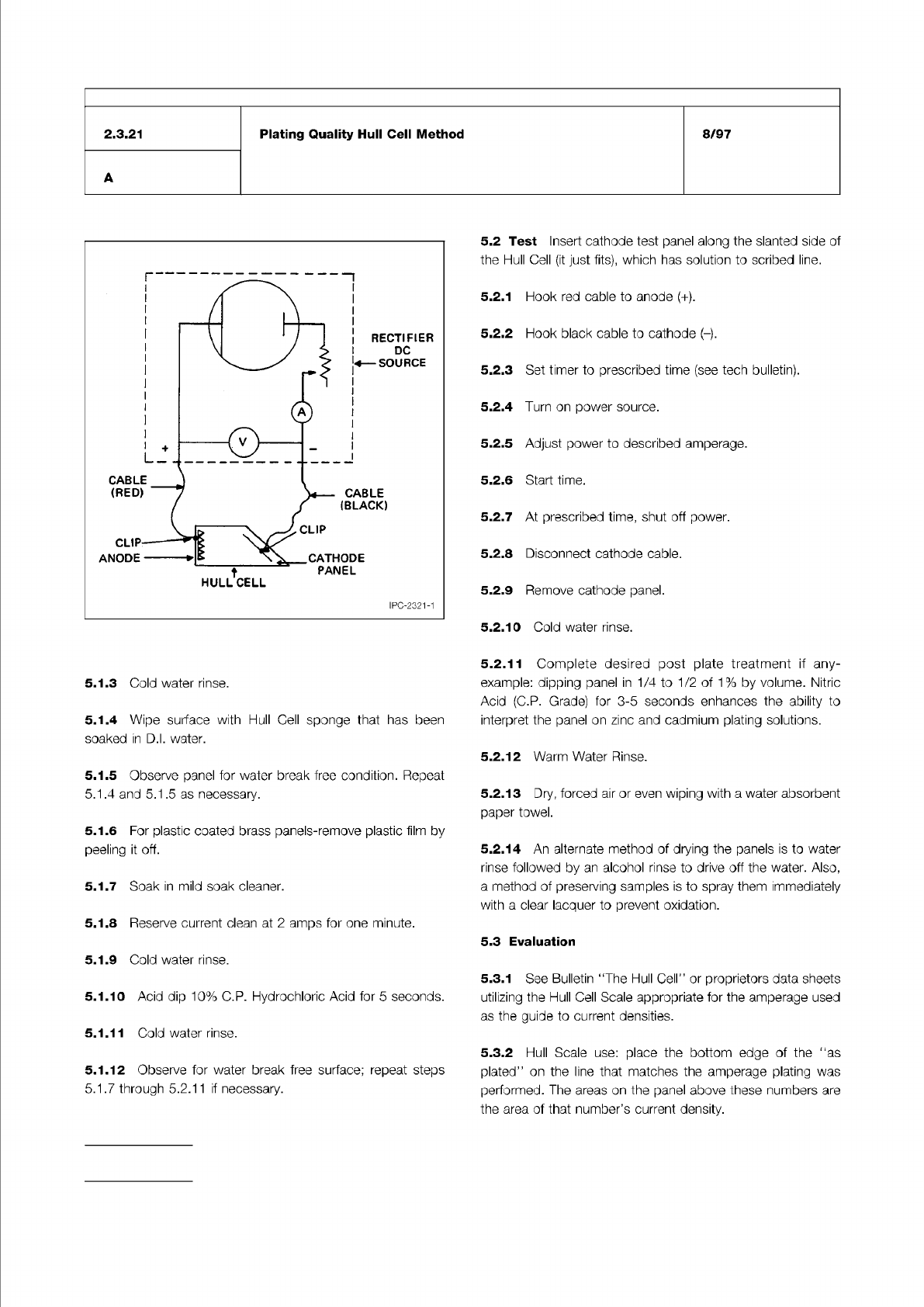
Figure 1 Hull Cell Hook Up
IPC-TM-650
Number
Subject Date
Revision
Page 2 of 3
2.3.21
Plating
Quality
Hull
Cell
Method
8/97
A
5.1.3
Cold
water
rinse.
5.1.4
Wipe
surface
with
Hull
Cell
sponge
that
has
been
soaked
in
D.l.
water.
5.1.5
Observe
panel
for
water
break
free
condition.
Repeat
5.1
.4
and
5.1
.5
as
necessary.
5.1.6
For
plastic
coated
brass
panels-remove
plastic
film
by
peeling
it
off.
5.1.7
Soak
in
mild
soak
cleaner.
5.1.8
Reserve
current
clean
at
2
amps
for
one
minute.
5.1.9
Cold
water
rinse.
5.1.10
Acid
dip
10%
C.P.
Hydrochloric
Acid
for
5
seconds.
5.1.1
1
Cold
water
rinse.
5.1.12
Observe
for
water
break
free
surface;
repeat
steps
5.1
.7
through
5.2.1
1
if
necessary.
5.2
Test
Insert
cathode
test
panel
along
the
slanted
side
of
the
Hull
Cell
(it
just
fits),
which
has
solution
to
scribed
line.
5.2.1
Hook
red
cable
to
anode
(+).
5.2.2
Hook
black
cable
to
cathode
(-).
5.2.3
Set
timer
to
prescribed
time
(see
tech
bulletin).
5.2.4
Turn
on
power
source.
5.2.5
Adjust
power
to
described
amperage.
5.2.6
Start
time.
5.2.7
At
prescribed
time,
shut
off
power.
5.2.8
Disconnect
cathode
cable.
5.2.9
Remove
cathode
panel.
5.2.10
Cold
water
rinse.
5.2.1
1
Complete
desired
post
plate
treatment
if
any-
example:
clipping
panel
in
1
/4
to
1
/2
of
1
%
by
volume.
Nitric
Acid
(C.P.
Grade)
for
3-5
seconds
enhances
the
ability
to
interpret
the
panel
on
zinc
and
cadmium
plating
solutions.
5.2.12
Warm
Water
Rinse.
5.2.13
Dry,
forced
air
or
even
wiping
with
a
water
absorbent
paper
towel.
5.2.14
An
alternate
method
of
drying
the
panels
is
to
water
rinse
followed
by
an
alcohol
rinse
to
drive
off
the
water.
Also,
a
method
of
preserving
samples
is
to
spray
them
immediately
with
a
clear
lacquer
to
prevent
oxidation.
5.3
Evaluation
5.3.1
See
Bulletin
1(The
Hull
Cell"
or
proprietors
data
sheets
utilizing
the
Hull
Cell
Scale
appropriate
for
the
amperage
used
as
the
guide
to
current
densities.
5.3.2
Hull
Scale
use:
place
the
bottom
edge
of
the
(1as
plated"
on
the
line
that
matches
the
amperage
plating
was
performed.
The
areas
on
the
panel
above
these
numbers
are
the
area
of
that
number's
current
density.