IPC-TM-650 EN 2022 试验方法--.pdf - 第179页
to accelerate extraction of ion ic so ils fro m poorly accessible places such as under surface mounted components. 5.3 Pro cedure 5.3.1 So lvent Sys tems Industry has e stablished two differ- ent standard test solutions …
4.4 Test Procedure
4.4.1
Carefully preclean all plasticware with deionized water
(16 MΩ-cm resistivity minimum) followed by a final rinse with
the extraction test solution.
4.4.2
Determine the surface area per Section 3.
4.4.3
Suspend the test specimen within an appropriately
sized funnel positioned over a graduated cylinder. Use clean
gloves when handling the samples to be tested.
4.4.4
Prepare the extraction solution volume using a general
ratio of no more than 10 mL: 1 cm
2
of area. Direct a fine
stream of freshly-deionized test solution on both sides of the
specimen, covering all board and component surfaces. Con-
tinue this process, slowly collecting the extraction solution.
The volume collected is not critical, but the total collected vol-
ume must be exactly recorded. A volume correction is made
in the calculation.
4.4.5
Pour the final measured volume into a plastic ware
beaker, stir and measure the resistivity/conductivity with either
a bridge probe or equivalent conductivity probe.
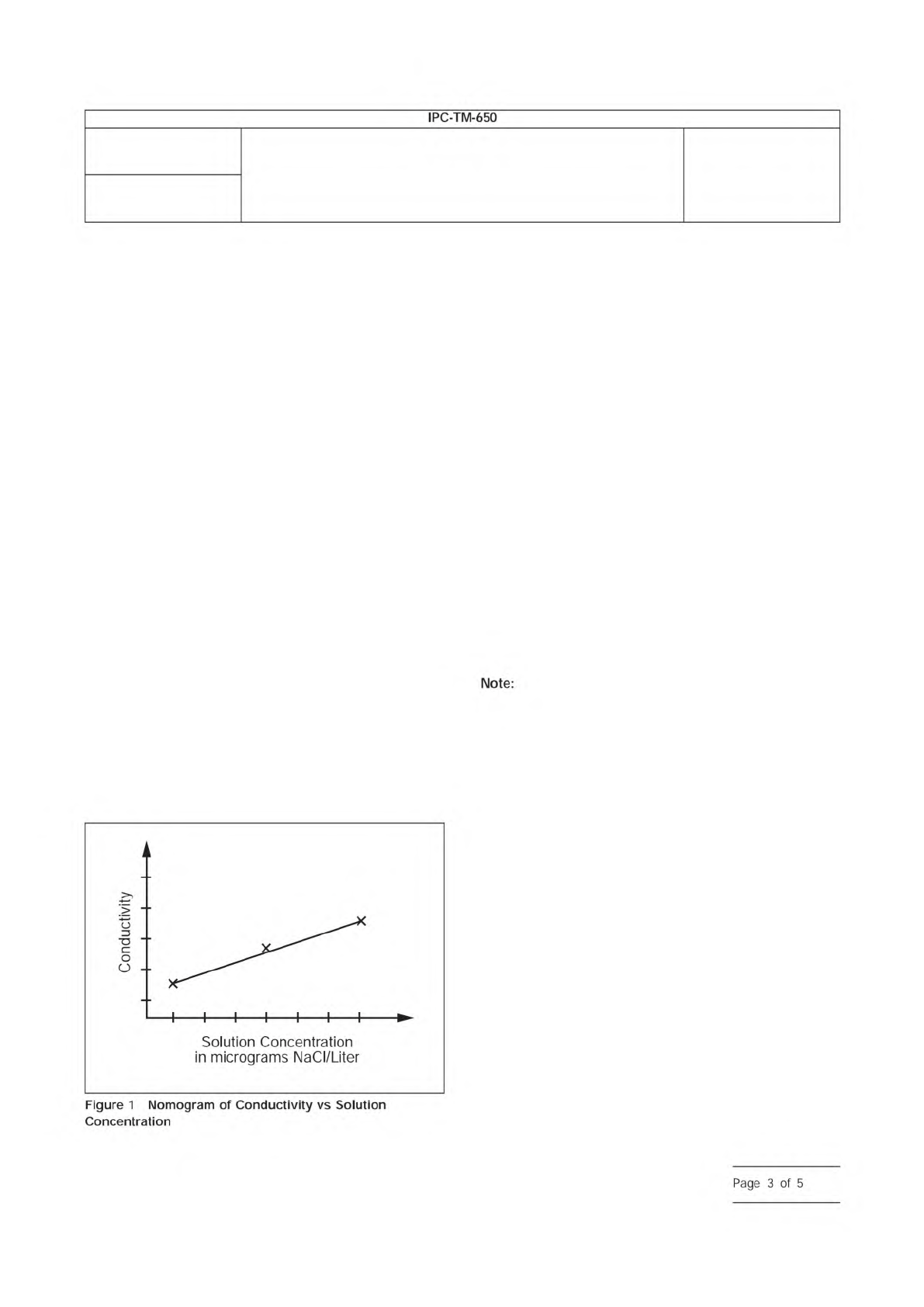
4.4.6
The resistivity/conductivity readings can be used to
convert the µg NaCl equivalent as follows:
1. Locate where the resistivity or conductivity intersects the
calibration curve on the X-axis (see Figure 1).
2. Extend a vertical line from the point of intersection to the
x-axis. Read and record µg/liter NaCl (M).
3. Multiply the concentration in µg/liter NaCl by the total liters
of test solution used (V). This result indicates the total µg of
NaCl equivalents removed from the printed wiring board
(T).
T = M x V
Where:
T = the numerical value of the total amount of NaCl equiva-
lents removed from the printed board, expressed in micro-
gram (µg);
M = the numerical value of the NaCl concentration of test
solution, expressed in microgram per liter (µg/L);
V = the numerical value of the total volume of test solution,
expressed in liter (L)
4. Divide the micrograms of NaCl equivalents by the area of
the printed wiring board or assembly (A). This yields the
conductivity factor in µg NaCl Eq./cm
2
.
T/A = µg NaCl Eq./cm
2
If samples read over the highest standard the sample
should be diluted by a known factor, retested and calculations
adjusted accordingly.
5 Dynamic Extraction Method
5.1 Description
In the dynamic method, a purified
2-propanol/DI water mixture is circulated into and out of a test
tank chamber containing the sample being tested. The mix-
ture exiting the test tank is passed through a conductivity cell
which measures the conductivity continuously. These conduc-
tivity values are integrated over the time of the extraction. The
mixture is then pumped through a resin deionization column
before it is recirculated back into the test tank. As ionic mate-
rials are extracted from the samples and then pumped out of
the cell, the conductivity of the solution will change dynami-
cally until all of the extractable ionic material has been
removed.
5.2 Test Equipment
Dynamic conductivity measurement
system includes a test tank, a temperature compensated con-
ductivity cell, ion exchange columns and a metering pump
connected together in a recirculating loop as described in 5.1.
The conductivity readings are integrated over the time of the
measurement by electronic integration. The equipment may
have the capability of heating the 2-propanol/DI water mixture
IPC-2325d-1
Number
2.3.25
Subject
Detection and Measurement of Ionizable Surface Contaminants by
Resistivity of Solvent Extract (ROSE)
Date
11/12
Revision
D
IPC-TM-650
Solution
Concentration
in
micrograms
NaCI/Liter
Note:
Figure
1
Nomogram
of
Conductivity
vs
Solution
Concentration
Page
3
of
5
to accelerate extraction of ionic soils from poorly accessible
places such as under surface mounted components.
5.3 Procedure
5.3.1 Solvent Systems
Industry has established two differ-
ent standard test solutions that are used worldwide:
75 % / 25 %, nominal v/v 2-propanol/DI water
50 % / 25 %, nominal v/v 2-propanol/DI water
Select the solution required by the specification (e.g., industry
standards, engineering drawing specifications, contract docu-
mentation, etc.).
5.3.2
Determine the surface area per Section 3.
5.3.3 Calibration
Once the fluid in the system has estab-
lished a stable level of conductivity, a precise quantity of a
sodium chloride calibration solution is injected into the test
solution in the test tank. This is done according to the calibra-
tion instructions provided by the manufacturer of the equip-
ment.
System calibration should be verified daily, when used.
5.3.4 Testing
Once the system has been calibrated or veri-
fied in accordance with 5.3.3, immerse the test specimen into
the sample tank. The test time should be in accordance with
the monitoring plan criteria (set time or auto-shutoff). Use
clean gloves when handling the samples to be tested. Finger
dirt contains ionic soils which may contribute to false read-
ings. During the course of the measurement, the conductivity
will rise from the initial baseline level and then gradually return.
When it has returned to the baseline level, no additional ionic
material can be removed and the measurement is complete.
5.4 Interpretation of Test Data
The number obtained
from this type of measurement indicates the total amount of
ionic material extracted from the entire sample in terms of
equivalent amounts of sodium chloride (assuming the calibra-
tion was done with sodium chloride). This should be divided
by the total surface area of the sample from which the ions
were extracted to determine the surface ionic density of the
original sample.
The following parameters must be
specified:
a) Solvent composition
b) Solvent volume for static method or flow rate for dynamic
method
c) Test temperature
d) Calibration of system
e) Sample area calculation
f) Test time
g) Equipment type and model number
The actual surface ionic density is most commonly calculated
by programming the area into the instrument’s microproces-
sor system. The total ionic amount will then be automatically
divided by the area to indicate surface ionic density in terms
of micrograms of sodium chloride equivalence per unit of sur-
face area (µg NaCl eq./cm
2
).
6 Static Extraction Method
6.1 Description
In the static extraction method, a mea-
sured volume of freshly deionized 2-propanol/DI water mixture
is introduced into the test tank and its resistivity (or conductiv-
ity) measured continuously while the 2-propanol/DI water mix-
ture is agitated. Once the system has been calibrated or veri-
fied in accordance with 6.3.3 and solution has been run
through the ion exchange columns, the test specimen is
immersed into the tank. The test time should be in accor-
dance with the monitoring plan criteria (set time or auto-
shutoff). Care must be taken not to handle the sample or any
of the appliances used to insert it into the tank. Finger dirt
contains ionic soils which may contribute to spurious read-
ings. During the course of the measurement, the conductivity
will rise from the initial baseline and then level off. When it has
stabilized and no additional ionic material can be removed
then the measurement is complete. After the test is completed
the solvent mixture is passed through ion exchange columns
to remove ionic materials and regenerate the 2-propanol/DI
water solvent mixture to its original high resistivity level for fur-
ther tests.
6.2 Test Equipment
A static conductivity measurement
system includes a test tank, a temperature-compensated
conductivity cell and monitor, means for solution agitation and
a means for removing, deionizing and re-introducing the sol-
vent mixture into the test tank before a new test is started.
The equipment may also have the capability of heating the
2-propanol/DI water mixture to accelerate and improve the
efficiency of extraction of ionic material from poorly accessible
regions, such as under surface-mounted components.
6.3 Procedure
6.3.1 Solvent Systems
See 5.3.1.
Number
2.3.25
Subject
Detection and Measurement of Ionizable Surface Contaminants by
Resistivity of Solvent Extract (ROSE)
Date
11/12
Revision
D
IPC-TM-650
—
Note:
Important
Parameters
Page
4
of
5
6.3.2
Determine the surface area per Section 3.
6.3.3 Calibration
A precise quantity of sodium chloride
calibration solution is injected into a designated volume of the
test solvent mixture in the sample measurement cell. This is
done according to the calibration or verification instructions
provided by the manufacturer of the equipment being used.
6.3.4 Testing
Once the system has been calibrated or veri-
fied in accordance with 6.3.3, the sample tank is filled as
directed by the procedures of the equipment manufacturer
and the test specimen is immersed in the tank. The minimum
starting resistivity for this type of equipment is machine
dependent. Use clean gloves when handling the samples to
be tested. Finger dirt contains ionic materials which may con-
tribute to spurious reading. During the course of the measure-
ment, the resistivity will fall continually as ionic material is
extracted into solution. If conductivity is being monitored, it will
initially be very low, rising continually as ionic material is dis-
solved from the sample. The test can be terminated when
there is no further change, in time, of the resistivity or conduc-
tivity function. This can be established electronically in most
commercially available equipment. The initial and final values
together with the volume of the solvent mixture in the test
tank, and sample surface area are used by the system to cal-
culate the ionic levels which were present on the sample sur-
face prior to the test.
6.3.5
Refer to the manufacturer’s equipment manual for
optimal operation.
6.4 Interpretation of Test Data
See 5.4.
7 Notes
7.1 Temperature
Higher solution temperatures will result
in higher levels of extracted ionic material. Most machines
have calculation algorithms which incorporate the solution
temperature. Refer to the machine documentation to under-
stand how temperature affects the ionic contamination read-
ing.
For process control testing, temperature should be set at a
constant value for periodic measurements. All calibrations of
the equipment should be made at the same solution tempera-
ture used to run the test.
7.2
It is critical to always use test solution with the same
composition of electronic grade 2-propanol (isopropyl
alcohol)/DI water for all comparative data discussions.
7.3
It is also suggested that a solution blank of 5 mL of
2-propanol/DI water be run at time of calibration to determine
the foundational cleanliness of the testing system.
7.4
Specific pieces of test equipment only have contamina-
tion output displays of two digits, if results are greater than or
equal to 100 the actual results will be lost and only the last
two digits will be displayed.
7.5
An extremely ‘‘dirty’’ sample can exceed machine maxi-
mums. Refer to the equipment documentation to determine
the maximum reading of the instrument.
8 References
Ionic Analysis of Circuit
Boards by Ion Chromatography
Circuit Board Ionic Cleanliness Measurement:
What Does It Tell Us?
Handbook and Guide to Supplement J-STD-
001
Number
2.3.25
Subject
Detection and Measurement of Ionizable Surface Contaminants by
Resistivity of Solvent Extract (ROSE)
Date
11/12
Revision
D
IPC-TM-650
IPC-TM-650,
Test
Method
2.3.28
IPC-TP-1113
IPC-HDBK-001
Page
5
of
5