IPC-TM-650 EN 2022 试验方法--.pdf - 第197页
IPC J-S TD-004 Material in this T est M ethods Manual was voluntarily establis hed by T echni cal Committees of IPC. Thi s mat erial is a dvisory only and its use or adaptation is entirely voluntary . IPC disclaims all l…
IPC-TM-650
Page 2 of 2
Number
2.3.32
Subject
Flux
Induced
Corrosion
(Copper
Mirror
Method)
Date
06/04
Revision
D
5.2.4
Immediately
also
place
one
drop
of
the
control
stan¬
dard
flux
adjacent
to
the
test
flux.
Do
not
allow
the
drops
to
touch.
5.2.5
Place
the
test
panel
in
a
horizontal
position
in
the
dust
free
cabinet
at
23
±
2
[73.4
±
3.6
°F]
and
50
±
5%
relative
humidity
for
24
±
1/2
hours.
5.2.6
At
the
end
of
the
24
hour
period,
remove
the
test
panel
and
remove
the
test
flux
and
control
standard
flux
by
immersion
in
clean
2-propanoL
5.3
Evaluation
5.3.1
Carefully
examine
the
test
panel
for
possible
copper
removal
or
discoloration.
5.3.2
See
J-STD-004
for
evaluation
criteria.
5.3.3
If
the
control
flux
fails
the
L
category,
repeat
the
entire
test
using
a
new
copper
mirror
test
panel.
5.3.4
Discoloration
of
the
copper
film
due
to
a
superficial
reaction
or
only
a
partial
reduction
of
the
copper
film
thickness
is
not
considered
a
failure.
5.3.5
A
number
of
chemicals
can
cause
failure
of
copper
mirror:
free
halides,
stronger
organic
and
inorganic
acids
and
free
amines.
6
Notes
6.1
Safety
Observe
all
appropriate
precautions
on
MSDS
for
chemicals
involved
in
this
test
method.
6.2
Preparation
of
Copper
Mirrors
6.2.1
Apply,
by
vacuum
deposition,
a
film
of
copper
metal
on
one
surface
of
a
flat
sheet
of
clear,
polished
glass.
6.2.2
Apply
a
uniform
thickness
of
approximately
50
nm,
and
assure
that
the
finished
mirror
permits
10
±
5%
transmis¬
sion
of
normal
incident
light
of
nominal
wave
length
of
500
nm.
This
may
be
determined
using
a
suitable
photoelectric
spectrophotometer.
6.2.3
Prevent
oxidation
of
the
copper
mirror
by
storing
in
a
closed
container
which
has
been
flushed
with
nitrogen.
IPC J-STD-004
Material in this Test Methods Manual was voluntarily established by Technical Committees of IPC. This material is advisory only
and its use or adaptation is entirely voluntary. IPC disclaims all liability of any kind as to the use, application, or adaptation of this
material. Users are also wholly responsible for protecting themselves against all claims or liabilities for patent infringement.
Equipment referenced is for the convenience of the user and does not imply endorsement by IPC.
Page 1 of 2
r
ASSOCIATION
CONNECTING
/
ELECTRONICS
INDUSTRIES
®
221
5
Sanders
Road
Northbrook,
IL
60062-6135
IPC-TM-650
TEST
METHODS
MANUAL
1
Scope
This
qualitative
test
method
is
designed
to
deter¬
mine
the
presence
of
chlorides
and
bromides
in
soldering
flux
by
visual
examination
after
placement
on
test
paper.
2
Applicable
Documents
Requirements
for
Soldering
Fluxes
3
Test
Specimen
A
minimum
of
1
0
ml
of
liquid
flux,
a
rep¬
resentative
container
of
solder
paste,
reflowed
solder
paste
flux,
extracted
solder
preform
flux
or
extracted
cored
wire
flux.
The
reflow/extraction
process
should
be
carried
out
in
accor¬
dance
with
J
-STD-004.
4
Apparatus
and
Reagents
4.1
Six
pieces
of
silver
chromate
test
paper
51
mm
x
51
mm.
4.2
250
ml
of
reagent
grade
2-propanoL
4.3
Six
glass
microscope
slides.
4.4
Spatula.
5
Procedures
5.1
Preparation
5.1.1
The
silver
chromate
paper
is
extremely
light
sensitive
and
must
be
stored
in
a
closed
container
away
from
light
until
used
for
testing.
5.1.2
To
avoid
contamination,
the
paper
must
be
handled
with
forceps
and
must
never
be
touched
with
bare
hands.
5.2
Test
for
Liquid
Flux
or
Flux
Extract
Solution
5.2.1
Place
one
drop
of
test
flux
or
flux
extract
(approxi¬
mately
0.05
ml)
on
each
piece
of
silver
chromate
test
paper.
Allow
the
droplet
to
remain
on
each
test
paper
for
a
minimum
of
1
5
seconds.
5.2.2
After
the
15
seconds,
immediately
immerse
each
test
paper
in
clean
2-propanol
to
remove
the
residual
organic
materials.
Number
2.3.33
Subject
Presence
of
Halides
in
Flux,
Silver
Chromate
Method
Date
Revision
06/04
D
Originating
Task
Group
Flux
Specifications
Task
Group
(5-24a)
5.2.3
Allow
each
test
paper
to
dry
and
examine
for
color
change.
5.3
Test
for
Paste
Flux
or
Solder
Paste
Flux
as
Obtained
from
the
Supplier
5.3.1
Clean
six
glass
microscope
slides
with
2-propanol
and
air
dry.
5.3.2
Moisten
each
piece
of
silver
chromate
reagent
paper
with
deionized
water.
5.3.3
Apply
a
wet
paper
to
each
glass
slide
and
remove
the
excess
water
with
blotting
paper.
5.3.4
Using
a
spatula,
apply
a
thin
coating
of
the
paste
flux
or
solder
paste
directly
onto
each
moist
reagent
paper.
5.3.5
Allow
the
paste
flux
or
solder
paste
to
remain
in
con¬
tact
with
the
paper
for
1
5
seconds,
then
remove
the
flux
with
2-propanol
or
other
appropriate
solvent
without
disturbing
the
paper.
5.3.6
Allow
each
test
paper
to
dry
and
examine
for
color
change.
5.4
Evaluation
Carefully
examine
each
test
sheet
for
pos¬
sible
color
change.
A
change
to
off-white
or
yellow-white
indi¬
cates
the
presence
of
chlorides
or
bromides
(see
Figure
1).
5.4.1
Interferences
A
number
of
chemicals
besides
free
halides
may
cause
test
failures.
(Representative
examples
are,
but
are
not
limited
to,
amines,
cyanides,
and
isocyanates.)
5.4.2
Certain
acidic
solutions
may
react
with
the
reagent
paper
to
produce
a
color
change
similar
to
that
obtained
with
chlorides
and
bromides.
When
a
color
change
is
observed,
it
is
advisable
to
check
the
acidity
of
the
affected
area
by
means
of
a
pH
indicating
paper.
If
pH
values
of
less
than
3
are
obtained,
the
presence
of
chlorides
and
bromides
should
be
verified
by
other
analytical
means.
5.4.3
It
is
possible
that
the
metal
present
in
a
solder
paste
sample
may
leave
a
white
residue
that
is
difficult
to
distinguish
A Certified Reference Material (CRM) covering the measuring
range of the application as described in 5.2.
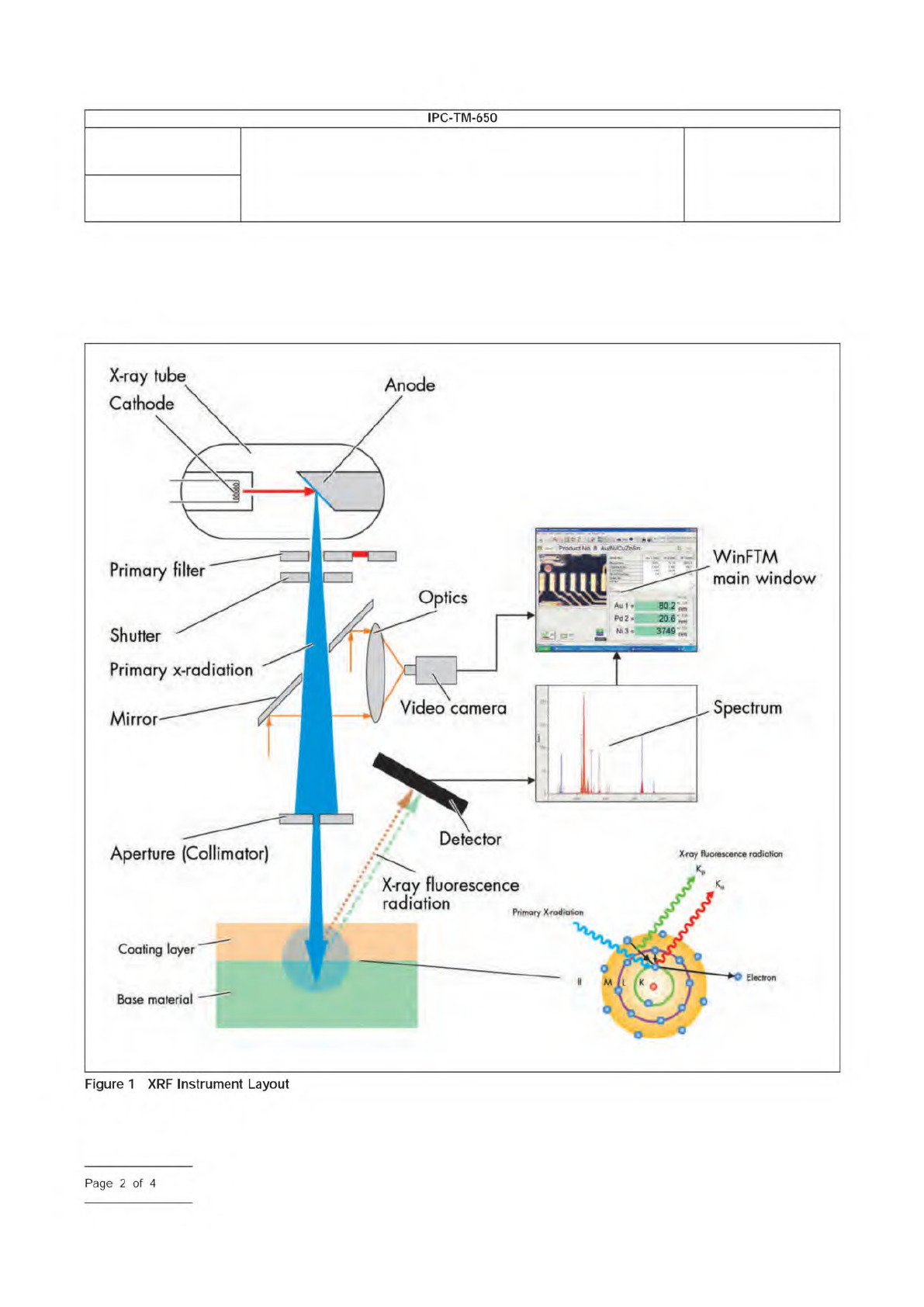
A typical instrument layout is shown in Figure 1.
IPC-2344-1
Number
2.3.44
Subject
Determination of Thickness and Phosphorus Content in
Electroless Nickel (EN) Layers by X-Ray Fluorescence (XRF)
Spectrometry
Date
03/16
Revision
IPC-TM-650
—
Anode
Primary
filter
Shutter
3749
Primary
x-radiation
Spectrum
Mirror
Detector
Aperture
(Collimator)
Primary
X-rodiation
Coating
laye
Electron
Base
material
X-ray
tube
Cathode
Video
camera
X<ay
fluorescence
radiation
WinFTM
main
window
Figure
1
XRF
Instrument
Layout
Page
2
of
4