IPC-TM-650 EN 2022 试验方法--.pdf - 第203页
IPC-TM-650 Number Subject Date Revision Page 2 of 2 2.4.1. 5 Determination of Treatment Transfer 5/95 A 5.3.3 Place the proper surface of the weight on the filter paper. 5.3.4 Grasping one end of the filter paper, pull t…
ANSI/IPC-MF-150
ANSI/IPC-CF-152
The Institute for Interconnecting and Packaging Electronic Circuits
2215 Sanders Road • Northbrook, IL 60062-6135
Material in this Test Methods Manual was voluntarily established by Technical Committees of the IPC. This material is advisory only
and its use or adaptation is entirely voluntary. IPC disclaims all liability of any kind as to the use, application, or adaptation of this
material. Users are also wholly responsible for protecting themselves against all claims or liabilities for patent infringement.
Equipment referenced is for the convenience of the user and does not imply endorsement by the IPC.
Page 1 of 2
IPC-TM-650
TEST
METHODS
MANUAL
Number
2.4.
1.5
Subject
Determination
of
Treatment
T
ransfer
Date
Revision
5/95
A
Originating
Task
Group
Treatment
Transfer
1
.0
SCOPE
1.1
This
procedure
describes
three
methods
to
determine
the
level
of
treatment
transfer
for
treated
copper
foil.
2
.0
APPLICABLE
DOCUMENTS
"Metal
Foil
for
Printed
Wiring
Applica¬
tions,
October
1991
,
current
revision.
4,
Composite
Foil
Specification,"
current
revision
3
.0
DEFINITION
3.1
Treatment
An
electro-mechanical
or
chemical
process
applied
to
one
or
both
sides
of
copper
foil
to
enhance
the
adhesion
of
the
foil
to
the
base
laminate.
3.2
Treatment
Transfer
Any
visible
bond
enhancement
that
has
transferred
from
the
surface
of
the
copper
foil
to
the
laminate
substrate.
4
.0
EQUIPMENT
4.1
For
the
Tape
Transfer
method
a
sample
of
the
foil
to
tested
152
mm
x
152
mm.
4.1.1
3M
Scotch
Brand
#600
Tape
19
mm
wide.
4.2
For
the
Strip
Transfer
method
a
representative
sample
of
foil,
pressed
to
four
plies
of
7628
FR-4
prepreg
to
produce
a
0.028
ml
laminate,
or
as
agreed
upon
by
user
and
supplier.
4.2.1
Etching
system
capable
of
removing
copper
foil
from
base
laminate.
4.3
For
the
Weight
and
Filter
Paper
method
a
sample
of
treated
foil
at
least
203
mm
x
51
mm.
4.3.1
#2
Filter
Paper
strips
at
least
76
mm
x
25
mm.
4.3.2
A
standardized
weight
of
250
grams
with
a
3/4
inch
surface
4.4
Visual
Acceptance
Standards
4.5
White
Background
5
.0
TEST
PROCEDURE
5.1
Tape
Transfer
Method
5.1.1
Each
copper
sample
being
tested
will
have
tape
19
mm
x
1
02
mm
applied
to
the
treatment
side
in
the
machine
direction
of
the
foil.
The
tape
should
be
firmly
applied
by
hand.
5.1.2
Remove
the
tape
by
quickly
pulling
on
one
end
at
an
acute
angle.
5.1
.3
The
tape
should
then
be
reaffixed,
adhesive
side
down
on
standard
white
paper.
5.2
Strip
Transfer
Method.
5.2.1
Image
a
line
on
the
laminate
to
a
minimum
of
1/8
inch
wide.
5.2.2
Etch,
clean
and
process
using
standard
industry
prac¬
tices
and
equipment.
If
preferred,
a
cut
or
sheared
sample
may
be
used.
5.2.3
Pull
the
strip
of
foil
back
1
inch
to
expose
the
area
directly
under
the
foil.
5.2.4
Visually
examine
this
area
by
placing
the
laminate
strip
against
a
white
background
and
comparing
the
amount
of
transfer
with
the
standard.
5.3
Weight
and
Filter
and
Paper
Method
5.3.1
Place
the
copper
foil
sample
on
a
firm,
flat
surface
with
the
treatment
side
up.
5.3.2
Place
the
#2
filter
paper
on
the
copper
foil
sample
with
the
rougher
side
of
the
paper
against
the
foil.
IPC-TM-650
Number
Subject Date
Revision
Page 2 of 2
2.4.1.
5
Determination
of
Treatment
Transfer
5/95
A
5.3.3
Place
the
proper
surface
of
the
weight
on
the
filter
paper.
5.3.4
Grasping
one
end
of
the
filter
paper,
pull
the
paper
and
the
weight
across
the
surface
of
the
foil
(going
in
the
transverse
direction,
across
the
grain)
for
a
distance
of
6〃.
6.0
EVALUATION
6.1
The
specimen
is
evaluated
for
treatment
transfer
as
fol¬
lows:
1
.
No
transfer
2.
Very
slight
transfer
3.
Slight
transfer
4.
Transfer
6.2
The
grading
scheme
listed
above
will
be
based
on
visual
comparison
of
an
acceptance
standard
agreed
upon
by
user
and
supplier.
ASTM D 3330
ASTM D 3359
Figure 1
1 mm100 m
The Institute for Interconnecting and Packaging Electronic Circuits
2215 Sanders Road • Northbrook, IL 60062-6135
Material in this Test Methods Manual was voluntarily established by Technical Committees of the IPC. This material is advisory only
and its use or adaptation is entirely voluntary. IPC disclaims all liability of any kind as to the use, application, or adaptation of this
material. Users are also wholly responsible for protecting themselves against all claims or liabilities for patent infringement.
Equipment referenced is for the convenience of the user and does not imply endorsement by the IPC.
Page 1 of 2
IPC-TM-650
TEST
METHODS
MANUAL
1
.0
Scope
This
test
method
establishes
a
procedure
for
determining
whether
the
adhesion
of
a
polymer
coating
to
an
inorganic
or
ceramic
substrate
is
above
an
adequate
level.
The
substrate
may
or
may
not
have
an
oxide
layer
on
the
sur¬
face.
The
test
can
be
inverted
and
used
for
determining
the
adhesion
of
a
metal
coating
to
a
polymer
film.
2
.0
Applicable
Documents
Test
Method
for
Peel
Adhesion
of
Pressure-
Sensitive
Tape
of
180°
Angle
Standard
Test
Methods
for
Measuring
Adhe¬
sion
by
Tape
Test
3
.0
Test
Specimen
The
test
specimen
shall
consist
of
the
coated
substrate.
A
control
should
also
be
prepared
using
a
mutually
agreed
upon
material
whose
results
from
this
test
are
known,
preferably
a
material
with
an
adhesion
classification
of
5.
At
least
3
test
specimens
should
be
prepared
for
each
material
of
interest.
4
.0
Apparatus
or
Material
4.1
25
mm
[1
.0
in]
wide
semitransparent
pressure
sensitive
tape
with
an
adhesion
strength
of
43
±
6
g/mm
[38
±
5
oz/in].
The
adhesion
should
not
change
more
than
6.5%
of
its
mean
value
within
12
months.
3M
Scotch
brand
#600
tape
has
been
found
to
be
acceptable
for
this
test.
4.2
Rubber
eraser
on
end
of
pencil.
4.3
A
light
source
is
helpful
in
determining
if
the
cut
has
been
made
all
the
way
through
the
polymer
to
the
substrate.
4.4
A
closed
boiling
water
bath.
5
.0
Procedure
5.1
Preparation
of
test
specimen.
Refer
to
ASTM
D
3330
and
ASTM
D
3359.
5.1.1
Prepare
and
clean
the
substrate
according
to
the
manufacturer's
recommended
procedure.
5.1.2
Prime
the
surface
with
the
manufacturer's
recom¬
Number
2.4.1.
6
Subject
Adhesion,
Polymer
Coating
Date
Revision
7/95
Originating
Task
Group
Deposited
Dielectric
Task
Group
(C-13a)
mended
adhesion
promoter,
if
required.
5.1.3
Apply
a
10
jim
to
25
gm
(measured
after
processing
is
complete)
coating
onto
the
surface
of
the
substrate
using
the
manufacturer's
recommended
procedure.
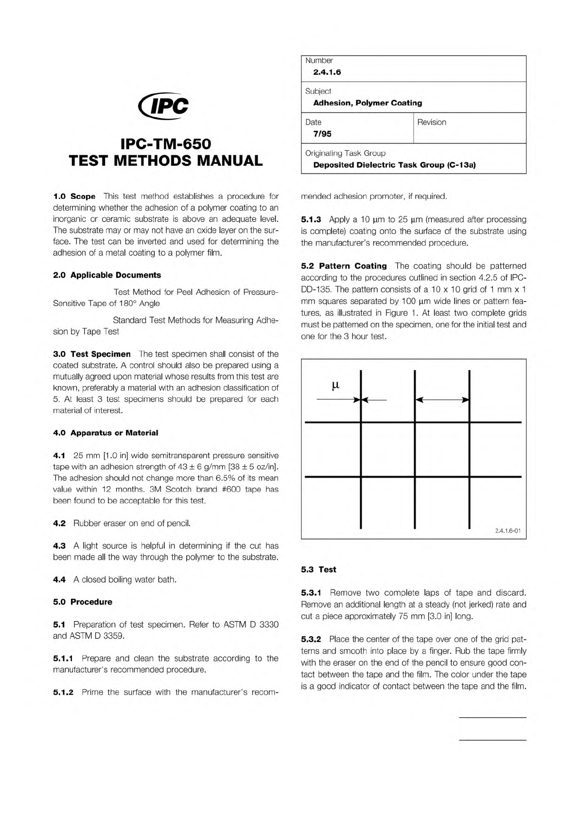
5.2
Pattern
Coating
The
coating
should
be
patterned
according
to
the
procedures
outlined
in
section
4.2.5
of
IPC-
DD-135.
The
pattern
consists
of
a
1
0
x
1
0
grid
of
1
mm
x
1
mm
squares
separated
by
1
00
|im
wide
lines
or
pattern
fea¬
tures,
as
illustrated
in
Figure
1
.
At
least
two
complete
grids
must
be
patterned
on
the
specimen,
one
for
the
initial
test
and
one
for
the
3
hour
test.
>
<
——
<
>
2.4.1.6-01
5.3
Test
5.3.1
Remove
two
complete
laps
of
tape
and
discard.
Remove
an
additional
length
at
a
steady
(not
jerked)
rate
and
cut
a
piece
approximately
75
mm
[3.0
in]
long.
5.3.2
Place
the
center
of
the
tape
over
one
of
the
grid
pat¬
terns
and
smooth
into
place
by
a
finger.
Rub
the
tape
firmly
with
the
eraser
on
the
end
of
the
pencil
to
ensure
good
con¬
tact
between
the
tape
and
the
film.
The
color
under
the
tape
is
a
good
indicator
of
contact
between
the
tape
and
the
film.