IPC-TM-650 EN 2022 试验方法--.pdf - 第226页
/ Figure 1 IPC-TM-650 Number Subject Date Revision Page 2 of 3 2.4.8.3 Peel Strength of Metallic Clad Laminate at Elevated Temperature (Hot Air Method) 12/94 A Note: Peel values can be affected by the adhesive used to bo…
IPC-TM-650
The Institute for Interconnecting and Packaging Electronic Circuits
2215 Sanders Road • Northbrook, IL 60062-6135
Material in this Test Methods Manual was voluntarily established by Technical Committees of the IPC. This material is advisory only
and its use or adaptation is entirely voluntary. IPC disclaims all liability of any kind as to the use, application, or adaptation of this
material. Users are also wholly responsible for protecting themselves against all claims or liabilities for patent infringement.
Equipment referenced is for the convenience of the user and does not imply endorsement by the IPC.
Page 1 of 3
Number
IPC-TM-650
TEST
METHODS
MANUAL
1
.0
Scope
This
test
is
designed
to
determine
the
peel
strength
of
the
metal
cladding
to
the
base
laminate
while
exposed
to
elevated
temperature
by
means
of
heated
air
chamber;
and
to
evaluate
the
base
laminate
material
after
the
peel
strength
test
is
completed
for
degradation
due
to
the
conditioning.
2
.0
Applicable
Documents
Method
2.4.8.1,
Peel
Strength,
Keyhole
Method
5.8.3,
Peel
Strength
Test
Pattern
3
.0
Test
Specimens
3.1
Size
and
Configuration
Specimen
size
shall
be
50.8
x
50.8
mm
[2x2
in]
by
the
thickness
of
the
laminate.
Cladding
test
strips
shall
be
as
specified
(see
5.1
.2).
3.2
Quantity
and
Sampling
Unless
otherwise
specified,
specimens
shall
be
one
lengthwise
for
each
clad
side
and
one
crosswise
for
each
clad
side.
The
outside
25.4
mm
[1
in]
bor¬
der
of
the
parent
sheet
or
panel
shall
be
excluded.
4
.0
Apparatus
or
Material
4.1
Tensile
Tester
A
tensile
strength
tester
equipped
with
a
load
cell,
capable
of
measuring
to
the
nearest
0.0045kg
[0.01
lbs.]
and
a
light
load
wire
or
chain
and
clamp
at
least
457
mm
[1
8
in]
long
(its
weight
is
included
in
the
load
cell
cal¬
culation).
The
clamp
jaws
must
cover
the
entire
conductor
width
of
each
peel
strip
tab.
Any
equipment
or
apparatus
having
the
described
accuracy,
precision,
and
reproducibility
may
be
used.
4.2
Thermal
Chamber
An
enclosure
of
the
specimen
loca¬
tion
of
the
tester,
capable
of
maintaining
the
test
temperatures
as
specified,
to
within
3
℃
[5.4°F]-
4.3
Specimen
Hold-down
A
suitable
hold-down
clamping
system
equivalent
in
performance
to
that
defined
in
IPO-TM-
650,
Method
2.4.8.1.
4.4
Oven
Circulating
air
oven
capable
of
maintaining
125
±
2
℃
[257
±
3.6°F].
2.4.8.3
Subject
Peel
Strength
of
Metallic
Clad
Laminate
at
Elevated
Temperature
(Hot
Air
Method)
Date
Revision
12/94
A
Originating
Task
Group
MIL-P-13949
Test
Methods
Task
Group
(7-1
1b)
4.5
Timer
Timing
device
capable
of
timing
to
within
1
second.
4.6
Measuring
device
capable
of
measuring
from
0.0000
to
12.7
mm
[0.0000
to
0.50
in]
to
within
0.0127
mm
[0.0005
in].
4.7
Etching
system
capable
of
complete
removal
of
metal
cladding.
4.8
Etch
Resist
Materials
or
Systems
4.8.1
Printer's
tape,
or
equivalent,
of
the
specified
width
(see
5.1.4)
to
act
as
etch
resist
for
strip
formation.
4.8.2
Photo
resist
system
(printing,
developing,
and
strip¬
ping).
5
.0
Procedure
5.1
Specimen
Preparation
5.1.1
Cut
the
specimens
from
the
laminate
sample.
Speci¬
mens
shall
be
taken
no
closer
than
2.54
mm
[1
.0
in]
from
the
edge
of
the
laminate
sheet.
5.1.2
Specimens
shall
be
prepared
with
suitable
etch
resist
material
so
that
four
strips
of
3.18
mm
[0.125
in]
width
are
etched,
and
then
cleaned
and
processed
using
standard
industry
practices
and
equipment.
For
qualification
and
ref¬
eree
testing,
the
specimens
shall
be
photo-imaged
in
accor¬
dance
with
Method
5.8.3
of
IPC-TM-650,
except
that
tab
ends
are
optional.
Specimens
shall
be
etched
so
that
the
test
strips
on
one
specimen
are
in
one
direction
per
Figure
2.
Double
clad
lami¬
nate
shall
have
each
side
tested
using
separate
specimens.
The
opposite
side
cladding
shall
be
either
fully
removed
or
left
fully
clad.
Separate
samples
for
both
the
warp
and
fill
direc¬
tions
are
required
for
each
side.
For
referee
testing,
the
clad¬
ding
on
the
opposite
side
shall
not
be
removed.
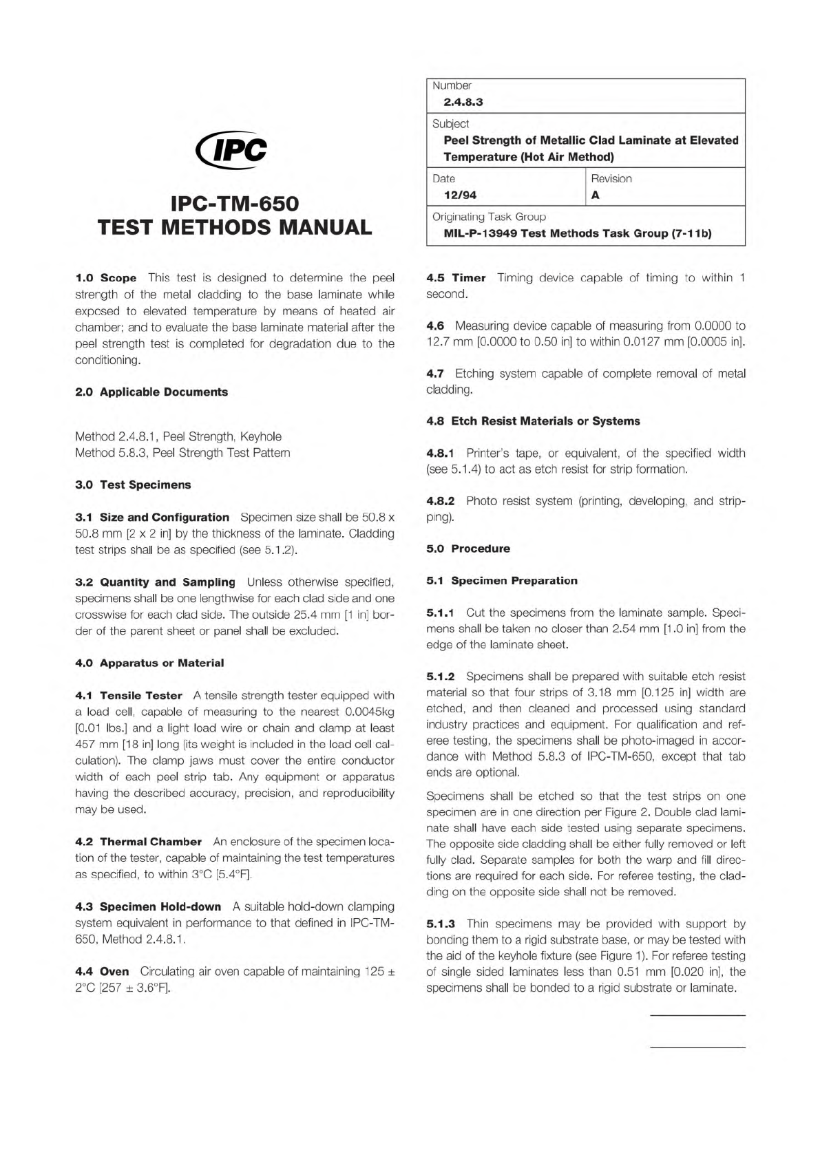
5.1.3
Thin
specimens
may
be
provided
with
support
by
bonding
them
to
a
rigid
substrate
base,
or
may
be
tested
with
the
aid
of
the
keyhole
fixture
(see
Figure
1).
For
referee
testing
of
single
sided
laminates
less
than
0.51
mm
[0.020
in],
the
specimens
shall
be
bonded
to
a
rigid
substrate
or
laminate.
/
Figure 1
IPC-TM-650
Number
Subject Date
Revision
Page 2 of 3
2.4.8.3
Peel
Strength
of
Metallic
Clad
Laminate
at
Elevated
Temperature
(Hot
Air
Method)
12/94
A
Note:
Peel
values
can
be
affected
by
the
adhesive
used
to
bond
the
specimen
to
the
rigid
substrate.
It
is
imperative
that
the
best
adhesive
be
found
for
the
type
of
materials
being
bonded
to
least
affect
the
true
peel
strength
value.
5.1.4
Peel
the
test
strip
back
approximately
12.7
mm
[0.5
in]
from
the
tab
end
(if
present).
5.1.5
Unless
otherwise
specified,
specimens
shall
be
pre¬
conditioned
by
baking
at
125℃
[257°F]
for
4
±
0.5
hours.
This
preconditioning
is
required
regardless
of
elevated
test
tem¬
perature
requirements
in
the
applicable
specification.
5.2
Measurement
5.2.1
Peel
Strength
Determination
5.2.1.
1
Preheat
the
test
chamber
to
the
specified
tempera¬
ture.
5.2.1.
2
Place
the
specimen
inside
the
test
chamber,
close
the
door
and
allow
the
specimen
to
remain
in
the
heated
chamber
for
60
+
6,
-0
minutes
before
performing
the
peel
test
at
the
applicable
elevated
temperature.
5.2.1.
3
After
attaching
the
clamp
to
each
peel
strip,
allow
the
specimen
to
stabilize
at
the
elevated
temperature
for
2.5
minutes
for
0.5
mm
[0.020
in]
thick
material
or
less,
and
5
minutes
for
material
thicker
than
0.5
mm
[0.020
in].
5.2.1.
4
Start
tester
and
apply
force
in
the
vertical
direction
at
50.8
mm
[2
in]
per
minute
until
peel
is
completed
or
test
strip
breaks
or
tears
(see
6.1).
5.2.1.
5
Observe
and
record
the
minimum
load
as
defined
by
Figure
2.
Measure
and
record
the
actual
width
of
the
metal
strip.
5.2.1.
6
If
the
full
width
of
the
test
strip
does
not
peel,
the
result
may
be
discarded
and
another
strip
tested.
5.2.1.
7
Perform
the
procedure
as
per
5.2.2
through
5.2.4
on
a
minimum
of
2
strips
per
side
per
specimen.
Any
unusual
event
or
irregularity
in
the
data
shall
be
cause
to
void
the
strip's
results
and
repeat
the
sequence
on
a
different
strip.
5.2.2
Determination
of
Degradation
Examine
the
speci¬
mens
using
normal
or
corrected
20/20
vision.
Record
the
presence
of
any
base
laminate
degradation,
including
loss
of
surface
resin,
discoloration,
resin
softening,
delamination,
blis¬
tering,
propagation
of
imperfections,
measling,
crazing,
or
voids.
5.3
Calculation
and
Report
5.3.1
Calculate
peel
strength
in
pounds
per
inch
width
using
the
formula:
.
Lm
lbs
"
屈
where:
Lm
=
Minimum
load
Ws=
Measured
width
of
peel
strip
5.3.2
Record
and
report
each
individual
peel
strength
value.
Average
the
individual
peel
strength
values
for
each
side
and
each
grain
direction
of
the
laminate
sampling.
For
example,
if
the
sampling
plan
called
for
one
specimen
per
side
and
per
grain
direction,
there
will
be
at
least
two
values
to
be
averaged
from
four
different
specimens.
5.3.3
Report
any
presence
of
laminate
degradation
as
observed
in
5.2.1
.3.
6.0
Notes
6.1
Test
strip
breaks
may
be
caused
by
either
superior
bond
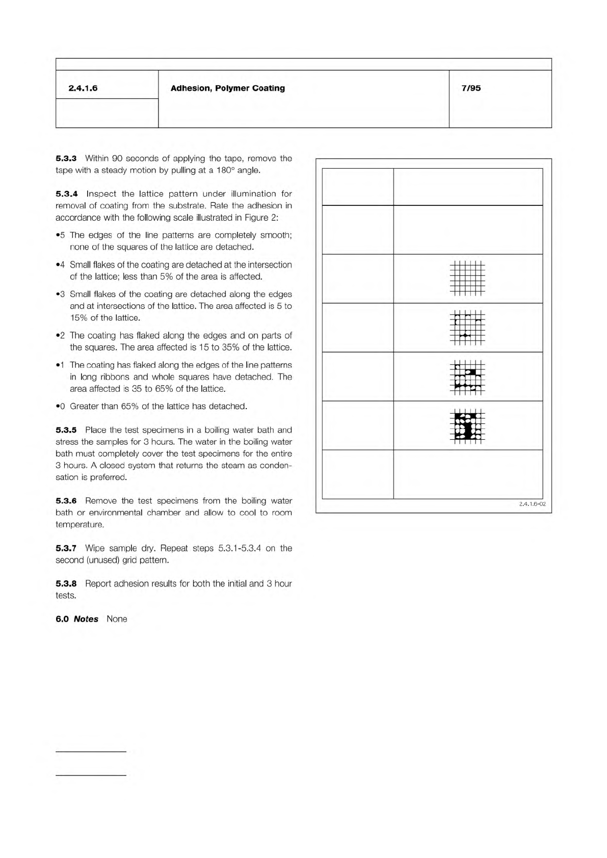
Figure 2
Classification
5 None
4
3
2
1
0 Greater than 65%
Surface of cross-cut area from
which flaking has occurred.
(Example for six paralleled cuts)
IPC-TM-650
Number
Subject Date
Revision
Page 2 of 2
2.4.1.
6
Adhesion,
Polymer
Coating
7/95
5.3.3
Within
90
seconds
of
applying
the
tape,
remove
the
tape
with
a
steady
motion
by
pulling
at
a
1
80°
angle.
5.3.4
Inspect
the
lattice
pattern
under
illumination
for
removal
of
coating
from
the
substrate.
Rate
the
adhesion
in
accordance
with
the
following
scale
illustrated
in
Figure
2:
•
5
The
edges
of
the
line
patterns
are
completely
smooth;
none
of
the
squares
of
the
lattice
are
detached.
•
4
Small
flakes
of
the
coating
are
detached
at
the
intersection
of
the
lattice;
less
than
5%
of
the
area
is
affected.
•
3
Small
flakes
of
the
coating
are
detached
along
the
edges
and
at
intersections
of
the
lattice.
The
area
affected
is
5
to
1
5%
of
the
lattice.
•
2
The
coating
has
flaked
along
the
edges
and
on
parts
of
the
squares.
The
area
affected
is
1
5
to
35%
of
the
lattice.
•
1
The
coating
has
flaked
along
the
edges
of
the
line
patterns
in
long
ribbons
and
whole
squares
have
detached.
The
area
affected
is
35
to
65%
of
the
lattice.
•
0
Greater
than
65%
of
the
lattice
has
detached.
5.3.5
Place
the
test
specimens
in
a
boiling
water
bath
and
stress
the
samples
for
3
hours.
The
water
in
the
boiling
water
bath
must
completely
cover
the
test
specimens
for
the
entire
3
hours.
A
closed
system
that
returns
the
steam
as
conden¬
sation
is
preferred.
5.3.6
Remove
the
test
specimens
from
the
boiling
water
bath
or
environmental
chamber
and
allow
to
cool
to
room
temperature.
5.3.7
Wipe
sample
dry.
Repeat
steps
5.3.1
-5.3.4
on
the
second
(unused)
grid
pattern.
5.3.8
Report
adhesion
results
for
both
the
initial
and
3
hour
tests.
—
"I
二
r
—
s
2.4.1.6-02
6.0
Notes
None