IPC-TM-650 EN 2022 试验方法--.pdf - 第250页
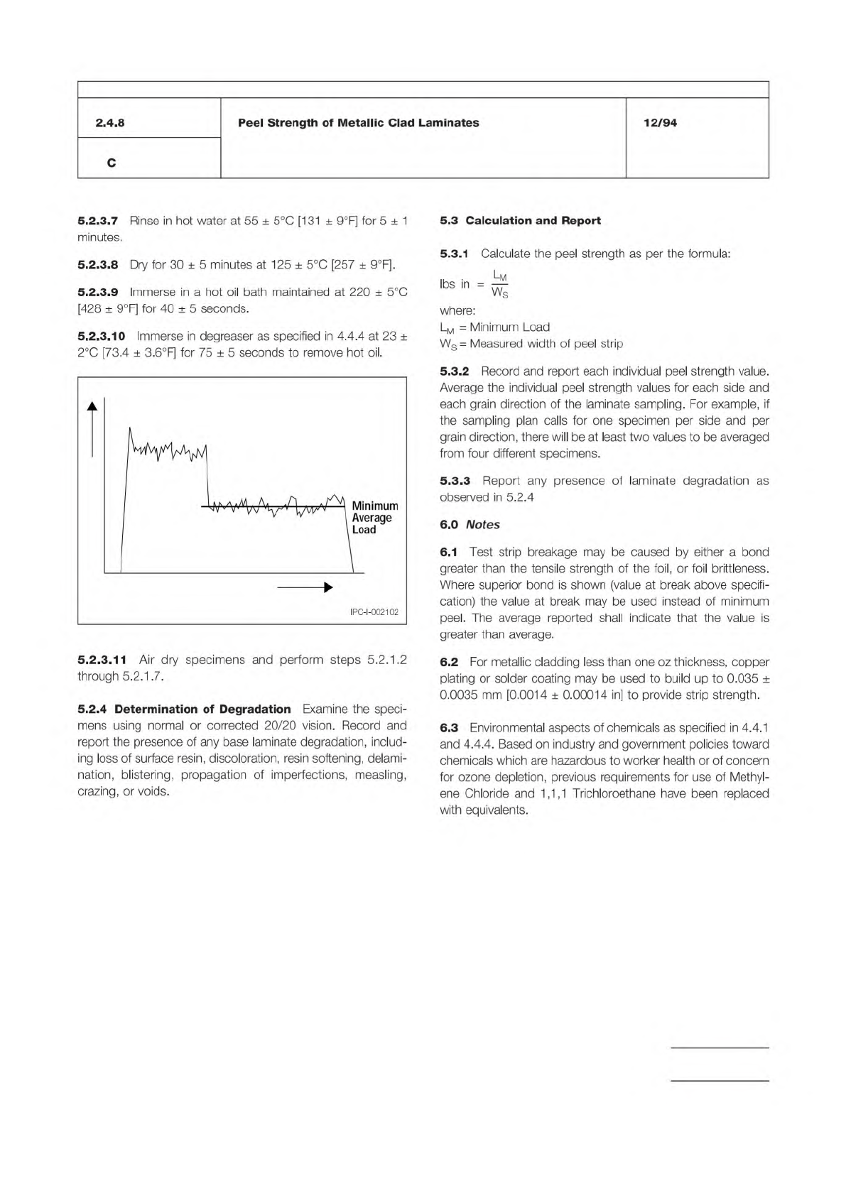
/ Figure 1 Multiple Failure Modes Peel Distance Load High Peel Strength Failure Mode Low Peel Strength Failure Mode IPC-TM-650 Number Subject Date Revision Page 3 of 3 2.4.8 Peel Strength of Metallic Clad Laminates 12/94…
Note:
IPC-TM-650
Number
Subject Date
Revision
Page 2 of 3
2.4.8
Peel
Strength
of
Metallic
Clad
Laminates
12/94
C
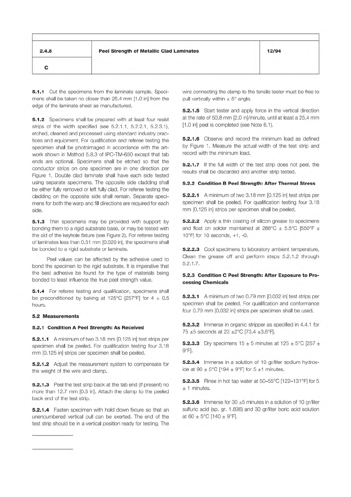
5.1.1
Cut
the
specimens
from
the
laminate
sample.
Speci¬
mens
shall
be
taken
no
closer
than
25.4
mm
[1
.0
in]
from
the
edge
of
the
laminate
sheet
as
manufactured.
5.1.2
Specimens
shall
be
prepared
with
at
least
four
resist
strips
of
the
width
specified
(see
5.2.
1.1,
5.2.2.
1
,
5.2.3.
1),
etched,
cleaned
and
processed
using
standard
industry
prac¬
tices
and
equipment.
For
qualification
and
referee
testing
the
specimen
shall
be
photoimaged
in
accordance
with
the
art¬
work
shown
in
Method
5.8.3
of
IPC-TM-650
except
that
tab
ends
are
optional.
Specimens
shall
be
etched
so
that
the
conductor
strips
on
one
specimen
are
in
one
direction
per
Figure
1
.
Double
clad
laminate
shall
have
each
side
tested
using
separate
specimens.
The
opposite
side
cladding
shall
be
either
fully
removed
or
left
fully
clad.
For
referee
testing
the
cladding
on
the
opposite
side
shall
remain.
Separate
speci¬
mens
for
both
the
warp
and
fill
directions
are
required
for
each
side.
5.1.3
Thin
specimens
may
be
provided
with
support
by
bonding
them
to
a
rigid
substrate
base,
or
may
be
tested
with
the
aid
of
the
keyhole
fixture
(see
Figure
2).
For
referee
testing
of
laminates
less
than
0.51
mm
[0.020
in],
the
specimens
shall
be
bonded
to
a
rigid
substrate
or
laminate.
Peel
values
can
be
affected
by
the
adhesive
used
to
bond
the
specimen
to
the
rigid
substrate.
It
is
imperative
that
the
best
adhesive
be
found
for
the
type
of
materials
being
bonded
to
least
influence
the
true
peel
strength
value.
5.1.4
For
referee
testing
and
qualification,
specimens
shall
be
preconditioned
by
baking
at
125℃
[257°F]
for
4
±
0.5
hours.
5.2
Measurements
5.2.1
Condition
A
Peel
Strength:
As
Received
5.2.1
.1
A
minimum
of
two
3.1
8
mm
[0.1
25
in]
test
strips
per
specimen
shall
be
peeled.
For
qualification
testing
four
3.18
mm
[0.125
in]
strips
per
specimen
shall
be
peeled.
5.2.
1.2
Adjust
the
measurement
system
to
compensate
for
the
weight
of
the
wire
and
clamp.
5.2.1
.3
Peel
the
test
strip
back
at
the
tab
end
(if
present)
no
more
than
12.7
mm
[0.5
in].
Attach
the
clamp
to
the
peeled
back
end
of
the
test
strip.
5.2.1.
4
Fasten
specimen
with
hold
down
fixture
so
that
an
unencumbered
vertical
pull
can
be
exerted.
The
end
of
the
test
strip
should
be
in
a
vertical
position
ready
for
testing.
The
wire
connecting
the
clamp
to
the
tensile
tester
must
be
free
to
pull
vertically
within
±
5°
angle.
5.2.1.
5
Start
tester
and
apply
force
in
the
vertical
direction
at
the
rate
of
50.8
mm
[2.0
in]/minute,
until
at
least
a
25.4
mm
[1
.0
in]
peel
is
completed
(see
Note
6.1).
5.2.1.
6
Observe
and
record
the
minimum
load
as
defined
by
Figure
1
.
Measure
the
actual
width
of
the
test
strip
and
record
with
the
minimum
load.
5.2.1.
7
If
the
full
width
of
the
test
strip
does
not
peel,
the
results
shall
be
discarded
and
another
strip
tested.
5.2.2
Condition
B
Peel
Strength:
After
Thermal
Stress
5.2.2.1
A
minimum
of
two
3.18
mm
[0.125
in]
test
strips
per
specimen
shall
be
peeled.
For
qualification
testing
four
3.18
mm
[0.125
in]
strips
per
specimen
shall
be
peeled.
5.2.2.2
Apply
a
thin
coating
of
silicon
grease
to
specimens
and
float
on
solder
maintained
at
288℃
±
5.5℃
[550°
F
土
10°F]
for
10
seconds,
+1,-0.
5.2.2.3
Cool
specimens
to
laboratory
ambient
temperature,
Clean
the
grease
off
and
perform
steps
5.2.1
.2
through
5.2.1.
7.
5.2.3
Condition
C
Peel
Strength:
After
Exposure
to
Pro¬
cessing
Chemicals
5.2.3.1
A
minimum
of
two
0.79
mm
[0.032
in]
test
strips
per
specimen
shall
be
peeled.
For
qualification
and
conformance
four
0.79
mm
[0.032
in]
strips
per
specimen
shall
be
used.
5.2.3.2
Immerse
in
organic
stripper
as
specified
in
4.4.1
for
75
±5
seconds
at
23
±2℃
[73.4
±3.6°F]-
5.2.3.3
Dry
specimens
15
±
5
minutes
at
125
±
5
℃
[257
±
9°F]-
5.2.3.4
Immerse
in
a
solution
of
10
gr/liter
sodium
hydrox¬
ide
at
90
土
5
℃
[194
±
9°F]
for
5
±1
minutes.
5.2.3.S
Rinse
in
hot
tap
water
at
50-55℃
[1
22-1
31
°F]
for
5
±
1
minutes.
5.2.3.6
Immerse
for
30
±5
minutes
in
a
solution
of
1
0
gr/liter
sulfuric
acid
(sp.
gr.
1
.836)
and
30
gr/liter
boric
acid
solution
at
60
土
5
℃
[140
±
9°F].
/
Figure 1 Multiple Failure Modes
Peel Distance
Load
High Peel Strength
Failure Mode
Low Peel Strength
Failure Mode
IPC-TM-650
Number
Subject Date
Revision
Page 3 of 3
2.4.8
Peel
Strength
of
Metallic
Clad
Laminates
12/94
C
5.2.3.7
Rinse
in
hot
water
at
55
±
5
℃
[131
±
9°F]
for
5
±
1
minutes.
5.2.3.8
Dry
for
30
±
5
minutes
at
125
±
5
℃
[257
土
9°F]-
5.2.3.9
Immerse
in
a
hot
oil
bath
maintained
at
220
土
5
℃
[428
±
9°F]
for
40
±
5
seconds.
5.2.3.10
Immerse
in
degreaser
as
specified
in
4.4.4
at
23
±
2
℃
[73.4
±
3.6°F]
for
75
±
5
seconds
to
remove
hot
oil.
5.2.3.11
Air
dry
specimens
and
perform
steps
5.2.1
.2
through
5.2.1
.7.
5.2.4
Determination
of
Degradation
Examine
the
speci¬
mens
using
normal
or
corrected
20/20
vision.
Record
and
report
the
presence
of
any
base
laminate
degradation,
includ¬
ing
loss
of
surface
resin,
discoloration,
resin
softening,
delami¬
nation,
blistering,
propagation
of
imperfections,
measling,
crazing,
or
voids.
5.3
Calculation
and
Report
5.3.1
Calculate
the
peel
strength
as
per
the
formula:
..
.
Lm
M
m
=
画
where:
Lm
二
Minimum
Load
Ws=
Measured
width
of
peel
strip
5.3.2
Record
and
report
each
individual
peel
strength
value.
Average
the
individual
peel
strength
values
for
each
side
and
each
grain
direction
of
the
laminate
sampling.
For
example,
if
the
sampling
plan
calls
for
one
specimen
per
side
and
per
grain
direction,
there
will
be
at
least
two
values
to
be
averaged
from
four
different
specimens.
5.3.3
Report
any
presence
of
laminate
degradation
as
observed
in
5.2.4
6.0
Notes
6.1
Test
strip
breakage
may
be
caused
by
either
a
bond
greater
than
the
tensile
strength
of
the
foil,
or
foil
brittleness.
Where
superior
bond
is
shown
(value
at
break
above
specifi¬
cation)
the
value
at
break
may
be
used
instead
of
minimum
peel.
The
average
reported
shall
indicate
that
the
value
is
greater
than
average.
6.2
For
metallic
cladding
less
than
one
oz
thickness,
copper
plating
or
solder
coating
may
be
used
to
build
up
to
0.035
±
0.0035
mm
[0.0014
土
0.00014
in]
to
provide
strip
strength.
6.3
Environmental
aspects
of
chemicals
as
specified
in
4.4.1
and
4.4.4.
Based
on
industry
and
government
policies
toward
chemicals
which
are
hazardous
to
worker
health
or
of
concern
for
ozone
depletion,
previous
requirements
for
use
of
Methyl¬
ene
Chloride
and
1
,1
,1
Trichloroethane
have
been
replaced
with
equivalents.
IPC-TM-650
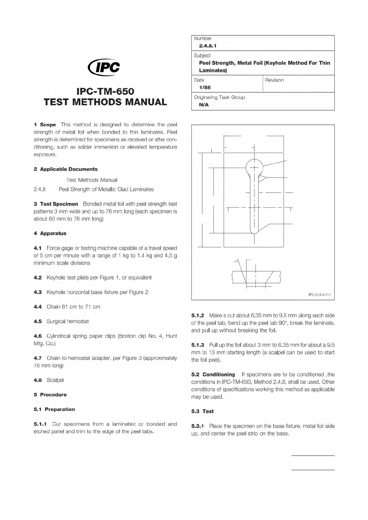
Figure 1 Keyhole Test Plate
8.5 cm
± 0.13 cm
‘‘A” ‘‘A”
3.8 cm ± 0.25 cm
2 cm
± 0.25 cm
13.5 cm
± 0.25 cm
8 cm ± 0.25 cm
1.9 cm
Blend entry edge of
hole into bevel of slot
0.4 cm ± 0.013 cm (Slot)
R
0.3 cm thick
AL Alloy
AA6061 T651
Pl
18 ± 2
0.41 cm Ref.
Section “A”-“A” Bevel detail 4x
+ 0.02 cm
- 0.013 cm
dia. hole
o
o
The Institute for Interconnecting and Packaging Electronic Circuits
2215 Sanders Road • Northbrook, IL 60062-6135
Material in this Test Methods Manual was voluntarily established by Technical Committees of the IPC. This material is advisory only
and its use or adaptation is entirely voluntary. IPC disclaims all liability of any kind as to the use, application, or adaptation of this
material. Users are also wholly responsible for protecting themselves against all claims or liabilities for patent infringement.
Equipment referenced is for the convenience of the user and does not imply endorsement by the IPC.
Page 1 of 3
IPC-TM-650
TEST
METHODS
MANUAL
1
Scope
This
method
is
designed
to
determine
the
peel
strength
of
metal
foil
when
bonded
to
thin
laminates.
Peel
strength
is
determined
for
specimens
as
received
or
after
con¬
ditioning,
such
as
solder
immersion
or
elevated
temperature
exposure.
2
Applicable
Documents
Test
Methods
Manual
2
.4.8
Peel
Strength
of
Metallic
Clad
Laminates
3
Test
Specimen
Bonded
metal
foil
with
peel
strength
test
patterns
3
mm
wide
and
up
to
76
mm
long
(each
specimen
is
about
60
mm
to
76
mm
long)
4
Apparatus
4.1
Force
gage
or
testing
machine
capable
of
a
travel
speed
of
5
cm
per
minute
with
a
range
of
1
kg
to
1
.4
kg
and
4.5
g
minimum
scale
divisions
4.2
Keyhole
test
plate
per
Figure
1
,
or
equivalent
4.3
Keyhole
horizontal
base
fixture
per
Figure
2
4.4
Chain
61
cm
to
71
cm
4.5
Surgical
hemostat
4.6
Cylindrical
spring
paper
clips
(Boston
clip
No.
4,
Hunt
Mfg.
Co.)
4.7
Chain
to
hemostat
adapter,
per
Figure
3
(approximately
76
mm
long)
4.8
Scalpel
5
Procedure
5.1
Preparation
5.1.1
Cut
specimens
from
a
laminated
or
bonded
and
etched
panel
and
trim
to
the
edge
of
the
peel
tabs.
Number
2.4.8.1
Subject
Peel
Strength,
Metal
Foil
(Keyhole
Method
For
Thin
Laminates)
Date
Revision
1/86
Originating
Task
Group
N/A
5.1
.2
Make
a
cut
about
6.35
mm
to
9.5
mm
along
each
side
of
the
peel
tab,
bend
up
the
peel
tab
90°,
break
the
laminate,
and
pull
up
without
breaking
the
foil.
5
J
.3
Pull
up
the
foil
about
3
mm
to
6.35
mm
for
about
a
9.5
mm
to
13
mm
starting
length
(a
scalpel
can
be
used
to
start
the
foil
peel).
5.2
Conditioning
If
specimens
are
to
be
conditioned
,the
conditions
in
IPC-TM-650,
Method
2.4.8,
shall
be
used.
Other
conditions
of
specifications
working
this
method
as
applicable
may
be
used.
5.3
Test
5.3.1
Place
the
specimen
on
the
base
fixture,
metal
foil
side
up,
and
center
the
peel
strip
on
the
base.