IPC-TM-650 EN 2022 试验方法--.pdf - 第289页
Notes IPC-TM-650 Page 3 of 3 Number 2.4.18.1 Revision A Subject Tensile Strength and Elongation, In-House Plating Date 05/04 5.3.5.1 Activate cross head to break sample and make cal¬ culations of tensile strength in Mpa …
IPC-TM-650
Page 2 of 3
Number
2.4.18.1
Revision
A
Subject
Tensile
Strength
and
Elongation,
In-House
Plating
Date
05/04
5.1.
1.8
Inspect
samples
and
discard
those
with
nicks
or
pinholes
in
the
gage
length.
Specimens
should
be
smooth
and
undistorted
without
scratches
from
the
plate
in
the
gage
length.
5.1.2
Cut
Method
5.
1.2.1
Clean
the
stainless
steel
panel
using
a
standard
acid
or
alkali
cleaner
(preferably
reverse
current)
and
verify
by
per¬
forming
a
water-break
test
to
insure
cleanliness.
5.1.
2.2
Plate
the
panel
with
a
current
density
equivalent
to
production
current
density
to
a
thickness
of
0.05
mm
to
0.1
mm
[0.00197
in
to
0.00394
in].
5.
1.2.3
Remove
the
copper
from
the
stainless
steel
by
lifting
a
corner
of
the
sample
with
a
knife
or
razor
exercising
care
not
to
bend
or
in
any
way
damage
the
sample.
Cut
away
and
dis¬
card
the
outside
2.5
cm
[0.984
in]
of
the
border
of
the
sample.
5.1.2.4
Cut
the
specimens
(five
lengthwise
and
five
cross¬
wise)
using
the
sample
cutter.
Samples
shall
be
smooth,
undistorted
(wrinkle
free),
and
free
of
pinholes,
nicks,
and
scratches.
5.2
Pre-Test
Bake
Bake
all
specimens
at
125
±
5
[257
°F
±
9
°F]
for
four
-
six
hours,
then
allow
the
samples
to
cool
to
room
temperature.
5.3
Test
5.3.1
Mark
Gage
Mark
or
otherwise
note
a
50
mm
[1
.97
in]
gage
length
to
the
nearest
0.01
mm
[0.000394
in].
5.3.2
Weighing
Samples
Weigh
tensile
sample
to
at
least
the
nearest
milligram
(0.001
gm).
Record
the
weight
and
cal¬
culate
the
mean
average
cross-sectional
area.
Note:
The
den¬
sity
of
electrodeposited
copper
is
8.909
g/cc
or
8909
g/mm3.
Mean
average
thickness
in
millimeters
=
Weight
of
tensile
sample
in
grams
Area
of
tensile
sample
in
mm2
x
density
of
copper
in
g/mm3
Mean
average
cross-sectional
area
in
mm2
=
Weight
of
tensile
sample
in
grams
Length
of
tensile
sample
in
mm
x
density
of
copper
in
mm
g/mm3
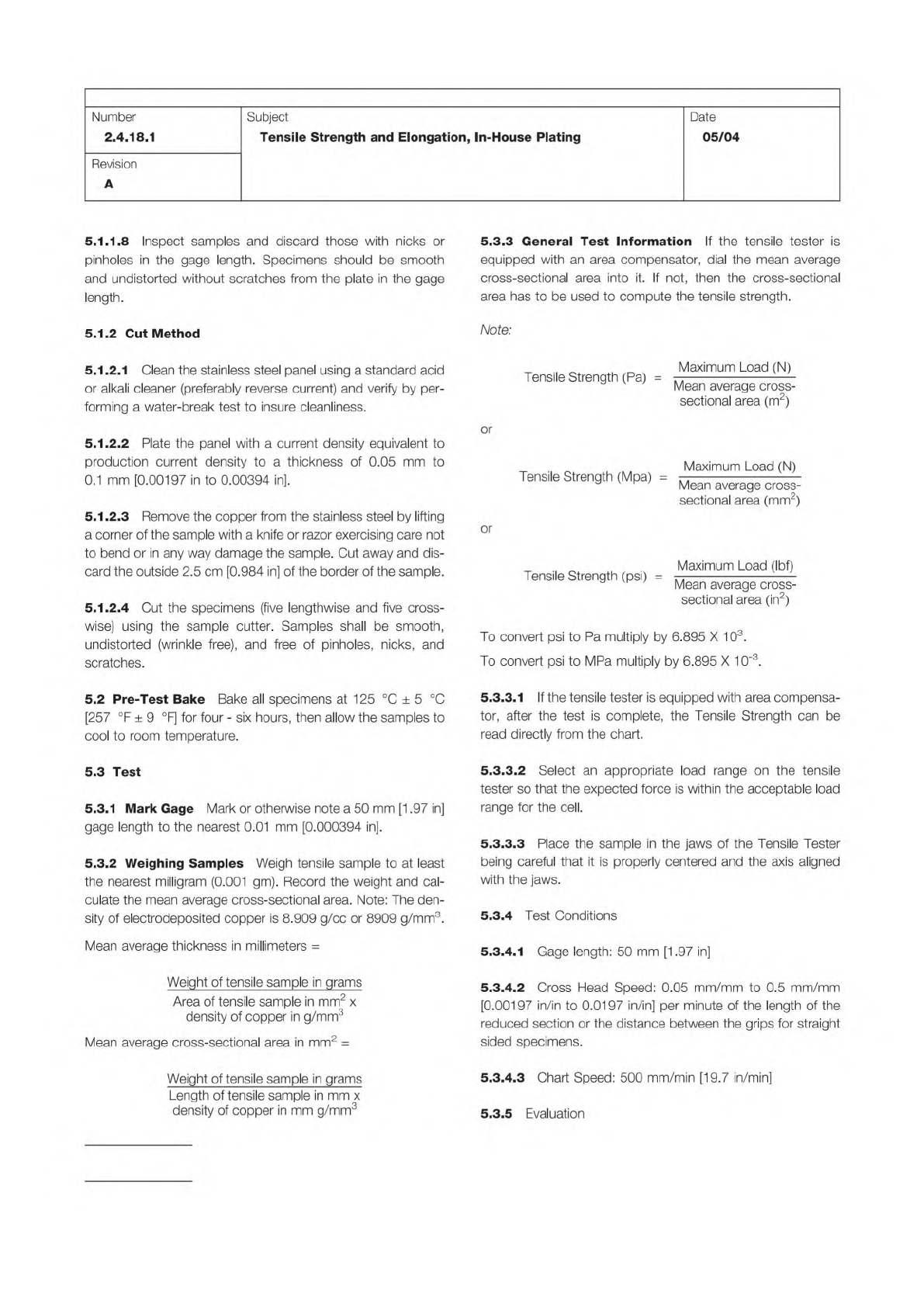
5.3.3
General
Test
Information
If
the
tensile
tester
is
equipped
with
an
area
compensator,
dial
the
mean
average
cross-sectional
area
into
it.
If
not,
then
the
cross-sectional
area
has
to
be
used
to
compute
the
tensile
strength.
Note:
or
Tensile
Strength
(Pa)
:
Maximum
Load
(N)
Mean
average
cross-
sectional
area
(m2)
Tensile
Strength
(Mpa)
Maximum
Load
(N)
Mean
average
cross-
sectional
area
(mm2)
or
Maximum
Load
(Ibf)
Tensile
Strength
(psi)
二
—
Mean
average
cross-
sectional
area
(in2)
To
convert
psi
to
Pa
multiply
by
6.895
X
103.
To
convert
psi
to
MPa
multiply
by
6.895
X
10-3.
5.3.3.
1
If
the
tensile
tester
is
equipped
with
area
compensa¬
tor,
after
the
test
is
complete,
the
Tensile
Strength
can
be
read
directly
from
the
chart.
5.3.3.2
Select
an
appropriate
load
range
on
the
tensile
tester
so
that
the
expected
force
is
within
the
acceptable
load
range
for
the
cell.
S.3.3.3
Place
the
sample
in
the
jaws
of
the
Tensile
Tester
being
careful
that
it
is
properly
centered
and
the
axis
aligned
with
the
jaws.
5.3.4
Test
Conditions
5.3.4.
1
Gage
length:
50
mm
[1
.97
in]
5.3.4.2
Cross
Head
Speed:
0.05
mm/mm
to
0.5
mm/mm
[0.00197
in/in
to
0.0197
in/in]
per
minute
of
the
length
of
the
reduced
section
or
the
distance
between
the
grips
for
straight
sided
specimens.
5.3.4.3
Chart
Speed:
500
mm/min
[19.7
in/min]
5.3.5
Evaluation
Notes
IPC-TM-650
Page 3 of 3
Number
2.4.18.1
Revision
A
Subject
Tensile
Strength
and
Elongation,
In-House
Plating
Date
05/04
5.3.5.1
Activate
cross
head
to
break
sample
and
make
cal¬
culations
of
tensile
strength
in
Mpa
and
elongation
in
%.
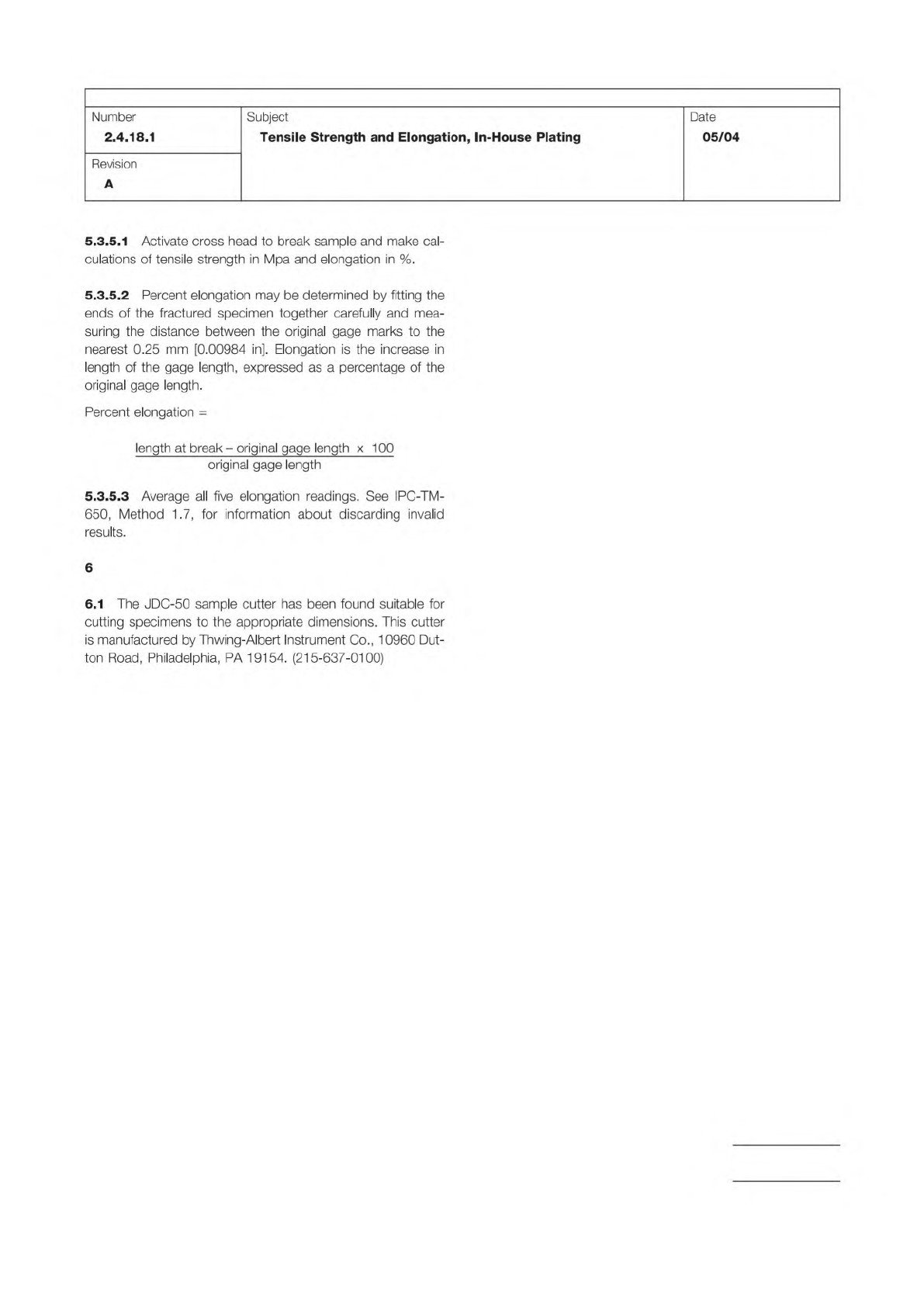
5.3.5.2
Percent
elongation
may
be
determined
by
fitting
the
ends
of
the
fractured
specimen
together
carefully
and
mea¬
suring
the
distance
between
the
original
gage
marks
to
the
nearest
0.25
mm
[0.00984
in].
Elongation
is
the
increase
in
length
of
the
gage
length,
expressed
as
a
percentage
of
the
original
gage
length.
Percent
elongation
=
length
at
break
-
original
gage
length
x
100
original
gage
length
5.3.5.3
Average
all
five
elongation
readings.
See
IPC-TM-
650,
Method
1.7,
for
information
about
discarding
invalid
results.
6
6.1
The
J
DC-50
sample
cutter
has
been
found
suitable
for
cutting
specimens
to
the
appropriate
dimensions.
This
cutter
is
manufactured
by
Thwing-Albert
Instrument
Co.,
10960
Dut¬
ton
Road,
Philadelphia,
PA
19154.
(215-637-0100)
IPC-MF-150
The Institute for Interconnecting and Packaging Electronic Circuits
2215 Sanders Road • Northbrook, IL 60062-6135
Material in this Test Methods Manual was voluntarily established by Technical Committees of the IPC. This material is advisory only
and its use or adaptation is entirely voluntary. IPC disclaims all liability of any kind as to the use, application, or adaptation of this
material. Users are also wholly responsible for protecting themselves against all claims or liabilities for patent infringement.
Equipment referenced is for the convenience of the user and does not imply endorsement by the IPC.
Page 1 of 2
IPC-TM-650
TEST
METHODS
MANUAL
1
.0
Scope
This
method
determines
the
hot
rupture
strength
of
foil
by
measuring
the
elevated
temperature
rupture
pressure
and
the
bulge
height
at
rupture.
2
.0
Applicable
Documents
3
.0
Apparatus
3.1
EMK
Model
HD550
Hot
Rupture
Testing
Machine,
or
equivalent,
with
fixed
apertures
for
17
micron
[1/2
oz.],
34
micron
[1
oz.]
and
68
micron
[2
oz.]
foil.
3.2
Mettler
balance,
Type
H16
Cap
80
gms,
or
equivalent;
and
hand
shears
or
precision
paper
cutter.
4
.0
Test
Specimen
Generation
4.1
Nine
(9)
test
specimens,
up
to
1
14
x
1
14
mm
[4.5
x
4.5
inches]
in
size,
are
required
for
each
sample
lot.
Larger
sample
panels
can
be
cut
into
specimen
squares
by
the
use
of
a
template
and
hand
shears.
4.2
Foil
samples
should
be
representative
of
foil
material
lots
as
defined
in
IPC-MF-150.
4.3
For
the
rupture
testing
of
in-house
PTH
copper,
electro¬
plate
a
sample
onto
a
smooth
stainless
steel
panel
per
exist¬
ing
PWB
shop
practice.
The
current
density
used
for
sample
preparation
should
be
equivalent
to
that
used
in
PTH
produc¬
tion
schedules.
The
deposited
thickness
should
be
held
within
±5%
of
0.018
mm
[1/2
oz],
0.035
mm
[1
oz.],
or
0.071
mm
[2
oz.]
foil.
4.4
Thermal
strain
relief
prior
to
rupture
testing
is
limited
to
times
and
temperatures
at
or
below
the
highest
heating
cycles
used
in
PWB
production.
5
.0
Test
Procedure
5.1
For
Inner-layer
foil
specimens,
record
the
date,
source,
lot
identification,
nominal
foil
thickness,
foil
type,
foil
grade,
and
the
aperture
diameter.
Number
2.4.18.2
Subject
Hot
Rupture
Strength,
Foil
Date
Revision
7/89
Originating
Task
Group
N/A
5.2
For
PTH
foil
specimens,
record
the
date,
source,
PTH
bath
type,
the
measured
thickness
and
the
aperture
diameter.
5.3
Aperture
Plates
Select
and
install
the
desired
aperture
plate
for
0.018
mm
[1/2
oz.],
0.035
mm
[1
oz.]
or
0.071
mm
[2
oz.]
test
specimen.
5.3.1
Aperture
diameters
are
fixed
at
22.2
+
3.2
mm
[0.875
+
0.125〃
r]
for
1/2
oz.
foil;
22.2
+
3.2
mm
[1
.875〃
+
0.125〃
r]
for
1
。乙
foil;
and
73
+
3.2
mm
[2.875〃
+
0.125〃
r]
for
2
o
乙
foil.
5.4
Flow
Control
Rate
of
flow
is
fixed
for
the
stress
rupture
test.
The
flow
rate
is
fixed
by
setting
the
source
pressure
at
100
psig,
sealing
the
system
and
adjusting
the
flow
to
reach
50
psig
in
5
seconds.
5.5
Test
Temperature
Set
the
test
equipment
for
tests,
in
turn,
at
room
temperature,
350°F
[1
77℃]
and
550°F
[288℃].
Temperature
stabilization
for
hot
tests
requires
a
minimum
of
1
5
minutes
at
temperature
(without
foil
specimens)
before
the
first
test
is
run.
5.6
Pressure
Set
the
test
pressure
regulator
at
the
source
pressure
limit.
Re-set
the
pressure
gauge
to
zero
and
set
the
Peak
and
Hold
modes.
5.7
Specimen
Insertion
Place
treated
foil
specimens
in
the
test
fixture
with
the
treated
side
up,
others
with
either
side
up.
Clamp
in
place
with
sufficient
force
to
provide
a
pressure-
tight
seal.
5.8
Height
Position
the
height
gauge
at
the
center
of
the
aperture.
Re-set
the
height
gauge
to
zero
and
set
the
Peak
and
Hold
modes.
5.9
Turn
on
the
test
pressure.
After
rupture
occurs,
turn
the
pressure
off,
and
remove
the
test
specimen.
5.10
Record
the
test
temperature,
the
pressure
at
rupture,
and
the
bulge
height
at
rupture.
With
digital
gauges,
take
Peak
readings
within
1
0
seconds
of
rupture
(because
of
an
inherent
decay
in
the
peak
signal).