IPC-TM-650 EN 2022 试验方法--.pdf - 第294页
Figure 1 S t r a i n S t r e s s IPC-TM-650 Number Subject Date Revision Page 3 of 3 2.4.18.3 Tensile Strength, Elongation, and Modulus 7/95 only this length is used in the calculation, otherwise the dis¬ tance between t…
IPC-TM-650
Number
Subject Date
Revision
Page 2 of 3
2.4.18.3
Tensile
Strength,
Elongation,
and
Modulus
7/95
4.7
Extension
Indicators
(optional)
Extension
indicators
(e.g.,
extensometers)
must
be
designed
as
to
minimize
stress
on
the
specimen
at
the
contact
points
of
the
specimen
and
the
indicator.
Clip
type
extensometers
are
not
recommended
for
this
reason.
Laser
extensometers
can
be
used
if
the
method
of
marking
the
specimen
does
not
induce
any
stress
or
strain
into
the
specimen
(e.g.,
scratching
the
specimen)
or
change
the
specimen
in
any
fashion
(e.g.,
heating
the
specimen).
4.8
Calibration
The
thickness
gauge
should
be
calibrated
every
six
months
using
standard
gauge
blocks.
The
blades
on
the
film
cutter
should
be
resharpened
or
replaced
at
least
once
a
year.
The
load
cell
on
the
tensile
tester
should
be
cali¬
brated
at
least
once
a
week
following
the
manufacturer
s
rec¬
ommended
procedure.
Also,
the
stops
which
control
the
ini¬
tial
grip
separation
should
be
checked
once
a
week.
5.0
Procedure
5.1
Operating
Conditions
The
tests
should
be
conducted
at
23
±
2
℃
and
50
±
5%
relative
humidity.
5.2
Preparation
of
Test
Specimens
5.2.1
The
test
specimens
should
be
conditioned
at
23
±
2
℃
and
50
±
5%
relative
humidity
for
not
less
than
24
hours
prior
to
testing.
Refer
to
ASTM
D
618.
5.2.2
The
free
films
are
placed
between
two
cover
sheets
of
clear
film
(Mylar®*
or
equivalent)
to
facilitate
handling
of
the
specimens.
5.2.3
Cut
at
least
10
specimens
76.20
mm
long
and
12.70
mm
wide.
No
specimen
shall
vary
by
more
than
2%
in
width
along
its
entire
length.
The
utmost
care
must
be
exercised
in
cutting
specimens
to
prevent
nicks
and
tears
along
the
edges
of
the
specimen
that
are
likely
to
cause
premature
failure.
If
the
properties
in
the
plane
of
the
film
are
not
isotropic
(e.g.,
the
films
were
not
prepared
by
spin
coating),
then
ten
films
must
be
cut
in
both
the
machine
direction
(MD)
and
transverse
direction
(TD).
5.4
Testing
5.4.1
Measure
and
record
the
thickness
of
the
test
speci¬
men
to
an
accuracy
of
0.1
gm
at
no
fewer
than
five
different
places
within
the
gauge
length
area.
Refer
to
ASTM
D
1
005
and
AST
D
2370.
5.4.2
Set
the
initial
gauge
length
(grip
separation)
at
25.4
mm
and
the
rate
of
grip
separation
at
5.08
mm/min.
5.4.3
Place
the
specimen
in
the
grips
of
the
testing
machine,
taking
care
to
align
the
long
axis
of
the
specimen
with
an
imaginary
line
joining
the
points
of
attachment
of
the
grips
to
the
machine.
The
specimen
should
be
aligned
as
per¬
fectly
as
possible
with
the
direction
of
pull
so
that
no
rotary
motion
that
may
induce
slippage
will
occur
in
the
grips.
Tighten
the
grips
evenly
and
firmly
to
the
degree
necessary
to
minimize
slipping
of
the
specimen
during
testing.
The
use
of
air
activated
grips
facilitates
the
mounting
of
the
specimen
in
the
grips.
5.4.4
Start
the
test
and
record
the
load
versus
extension.
5.4.5
Repeat
steps
5.4.1
-
5.4.4
for
each
series
of
ten
specimens.
5.5
Calculations
5.5.1
For
each
series
of
ten
specimens,
the
arithmetic
mean
and
standard
deviation
of
each
property
for
the
specimens
with
the
five
highest
tensile
strengths
shall
be
calculated
to
the
proper
number
of
significant
figures.
This
is
done
on
the
basis
that
the
expected
errors
(nicks
or
flaws
in
the
specimen,
breaks
within
the
grips,
specimen
slippage,
etc.)
would
all
tend
to
produce
lower
results.
The
standard
deviation
is
cal¬
culated
as
follows
and
reported
to
two
significant
figures:
N
/
N
\
2
怦
2-(中)
5-
丫
N(N-1)
where
Xi
is
the
value
of
a
single
observation
(i
=
1
through
N),
N
is
the
number
of
observations,
and
sx
is
the
estimated
stan¬
dard
deviation.
5.5.2
Tensile
Strength
Tensile
strength
is
calculated
by
dividing
the
load
at
break
by
the
original
minimum
cross-
sectional
area.
The
result
is
expressed
in
megapascals
(MPa)
and
reported
to
three
significant
figures.
tensile
strength
=
(load
at
break)
(original
width)
(original
thickness
5.5.3
Percent
Elongation
Percent
elongation
is
calculated
by
dividing
the
elongation
at
the
moment
of
rupture
by
the
ini¬
tial
gauge
length
and
multiplying
by
1
00.
When
gauge
marks
or
extensometers
are
used
to
define
a
specific
test
section,
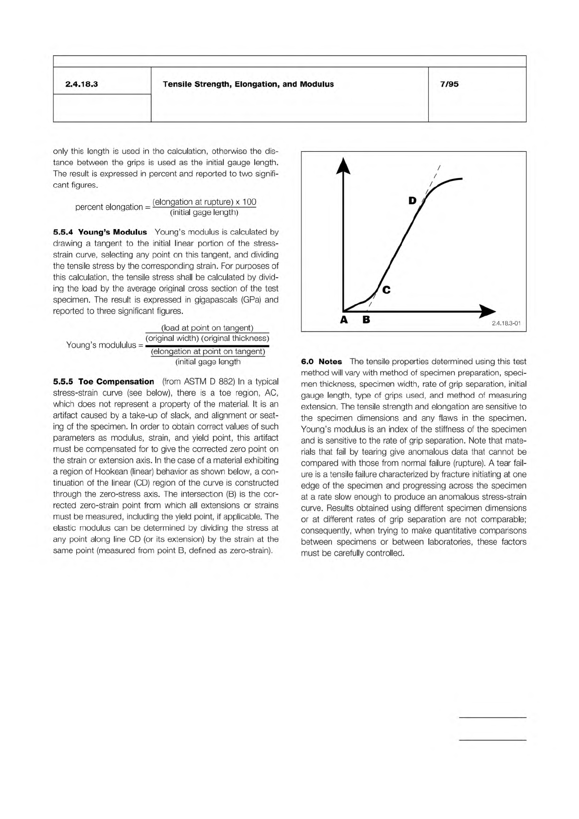
Figure 1
Strain
Stress
IPC-TM-650
Number
Subject Date
Revision
Page 3 of 3
2.4.18.3
Tensile
Strength,
Elongation,
and
Modulus
7/95
only
this
length
is
used
in
the
calculation,
otherwise
the
dis¬
tance
between
the
grips
is
used
as
the
initial
gauge
length.
The
result
is
expressed
in
percent
and
reported
to
two
signifi¬
cant
figures.
percent
elongation
=
(elorgator
at
rupture)
x
1
00
(initial
gage
length)
5.5.4
Young's
Modulus
Young's
modulus
is
calculated
by
drawing
a
tangent
to
the
initial
linear
portion
of
the
stress¬
strain
curve,
selecting
any
point
on
this
tangent,
and
dividing
the
tensile
stress
by
the
corresponding
strain.
For
purposes
of
this
calculation,
the
tensile
stress
shall
be
calculated
by
divid¬
ing
the
load
by
the
average
original
cross
section
of
the
test
specimen.
The
result
is
expressed
in
gigapascals
(GPa)
and
reported
to
three
significant
figures.
(load
at
point
on
tangent)
(original
width)
(original
thickness)
Young's
modululus
=
(elongation
at
point
on
tangent)
(initial
gage
length
5.5.5
Toe
Compensation
(from
ASTM
D
882)
In
a
typical
stress-strain
curve
(see
below),
there
is
a
toe
region,
AC,
which
does
not
represent
a
property
of
the
material.
It
is
an
artifact
caused
by
a
take-up
of
slack,
and
alignment
or
seat¬
ing
of
the
specimen.
In
order
to
obtain
correct
values
of
such
parameters
as
modulus,
strain,
and
yield
point,
this
artifact
must
be
compensated
for
to
give
the
corrected
zero
point
on
the
strain
or
extension
axis.
In
the
case
of
a
material
exhibiting
a
region
of
Hookean
(linear)
behavior
as
shown
below,
a
con¬
tinuation
of
the
linear
(CD)
region
of
the
curve
is
constructed
through
the
zero-stress
axis.
The
intersection
(B)
is
the
cor¬
rected
zero-strain
point
from
which
all
extensions
or
strains
must
be
measured,
including
the
yield
point,
if
applicable.
The
elastic
modulus
can
be
determined
by
dividing
the
stress
at
any
point
along
line
CD
(or
its
extension)
by
the
strain
at
the
same
point
(measured
from
point
B,
defined
as
zero-strain).
6.0
Notes
The
tensile
properties
determined
using
this
test
method
will
vary
with
method
of
specimen
preparation,
speci¬
men
thickness,
specimen
width,
rate
of
grip
separation,
initial
gauge
length,
type
of
grips
used,
and
method
of
measuring
extension.
The
tensile
strength
and
elongation
are
sensitive
to
the
specimen
dimensions
and
any
flaws
in
the
specimen.
Young's
modulus
is
an
index
of
the
stiffness
of
the
specimen
and
is
sensitive
to
the
rate
of
grip
separation.
Note
that
mate¬
rials
that
fail
by
tearing
give
anomalous
data
that
cannot
be
compared
with
those
from
normal
failure
(rupture).
A
tear
fail¬
ure
is
a
tensile
failure
characterized
by
fracture
initiating
at
one
edge
of
the
specimen
and
progressing
across
the
specimen
at
a
rate
slow
enough
to
produce
an
anomalous
stress-strain
curve.
Results
obtained
using
different
specimen
dimensions
or
at
different
rates
of
grip
separation
are
not
comparable;
consequently,
when
trying
to
make
quantitative
comparisons
between
specimens
or
between
laboratories,
these
factors
must
be
carefully
controlled.
Material in this Test Methods Manual was voluntarily established by Technical Committees of the IPC. This material is advisory only
and its use or adaptation is entirely voluntary. IPC disclaims all liability of any kind as to the use, application, or adaptation of this
material. Users are also wholly responsible for protecting themselves against all claims or liabilities for patent infringement.
Equipment referenced is for the convenience of the user and does not imply endorsement by the IPC.
Page 1 of 2
r
ASSOCIATION
CONNECTING
/
ELECTRONICS
INDUSTRIES
®
221
5
Sanders
Road
Northbrook,
IL
60062-6135
IPC-TM-650
TEST
METHODS
MANUAL
1
Scope
This
test
is
to
determine
the
tensile
strength
and
elongation
on
specimens
exposed
to
mechanical
loads.
2
Applicable
Documents
None
3
Test
Specimen
The
test
specimen
shall
consist
of
a
strip
of
flexible
material
152.4
mm
long
x
12.7
mm
wide.
A
mini¬
mum
of
10
specimens,
five
from
the
machine
direction,
and
five
from
the
transverse
direction,
shall
be
prepared.
4
Apparatus
4.1
Equipment
Tinius-Olson
Super
L
Tester
or
equivalent
(with
appropriate
load
cell).
The
machine
used
for
tension
test¬
ing
shall
be
in
current
calibration.
The
loads
used
in
determin¬
ing
tensile
strength
shall
be
within
the
loading
range
of
the
testing
machine.
4.2
Gripping
Devices
Various
types
of
gripping
devices
may
be
used
to
transmit
the
measured
load
applied
by
the
testing
machine
to
the
test
specimens.
To
ensure
axial
tensile
stress
within
the
gauge
length,
the
axis
of
the
test
specimen
should
coincide
with
the
centerline
of
the
heads
of
the
testing
machine.
4.3
Sample
Cutter
Thwing
Albert
Sample
Cutter,
Model
No.
JDC-50,
or
equivalent.
4.4
Etcher
4.5
Sander
4.6
Micrometer
with
0.0025
mm
resolution
4.7
Conditioning
chamber
or
work
area
23℃
±
2
℃,
50%
±
5%
RH
5
Procedure
5.1
Preparation
of
Specimens
Number
2.4.19
Subject
Tensile
Strength
and
Elongation,
Flexible
Printed
Wiring
Materials
Date
Revision
5/98
C
Originating
Task
Group
Flex
Peel
Strength
Test
Methods
Task
Group
(D-13A)
5.1.1
Condition
specimens
for
24
hours
at
23℃
±
2
℃
and
50%
±
5%
relative
humidity
(RH).
Stabilization
time
may
be
reduced
if
statistically
sound
evidence
has
been
generated
on
the
specific
product
line
to
support
shorter
conditioning
times
to
reach
equilibrium.
5.1.2
Cut
at
least
10
specimens,
152.4
mm
long
by
12.7
mm
wide,
using
a
precision
sample
cutter,
which
produces
smooth
and
undistorted
edges.
Specimens
may
be
sanded
on
the
edges
with
400-600
grit
emery
paper
to
further
smooth
the
edges
and
improve
the
repeatability
of
the
test.
5.2
Test
5.2.1
Measure
and
record
the
width
and
thickness
of
the
specimen
at
several
points
along
its
length.
Calculate
the
mini¬
mum
cross-sectional
area
using
the
measured
width.
For
coated
materials,
ignore
the
thickness
of
the
coating,
assumed
to
contribute
nothing
to
the
tensile
properties
of
the
composite,
and
use
the
nominal
substrate
thickness
for
the
cross-sectional
area
calculation.
5.2.2
Set
the
grip
separation
to
101.6
mm
and
the
rate
of
grip
separation
to
50.8
mm
per
minute.
5.2.3
Place
the
test
specimen
in
the
grips
of
the
testing
machine,
taking
care
to
align
it
with
the
centerline
of
the
grips.
There
should
be
no
slack
in
the
specimen.
5.2.4
Start
the
machine
and
record
load
versus
extension
(grip
separation).
5.3
Evaluation
5.3.1
Tensile
strength
shall
be
calculated
by
dividing
the
load
at
break
by
the
original
cross-sectional
area
of
the
speci¬
men.
Average
the
five
values
obtained
for
the
machine
direc¬
tion
samples
and
report
the
average.
Average
the
five
values
obtained
for
the
transverse
direction
samples
and
report
the
average.