IPC-TM-650 EN 2022 试验方法--.pdf - 第296页
IPC-TM-650 Page 2 of 2 Number 2.4.19 Subject Tensile Strength and Elongation, Flexible Printed Wiring Materials Date 5/98 Revision C 5.3.2 Elongation shall be calculated by the following for¬ mula: D2 ~ D1 T cc 0/ i— I .…
Material in this Test Methods Manual was voluntarily established by Technical Committees of the IPC. This material is advisory only
and its use or adaptation is entirely voluntary. IPC disclaims all liability of any kind as to the use, application, or adaptation of this
material. Users are also wholly responsible for protecting themselves against all claims or liabilities for patent infringement.
Equipment referenced is for the convenience of the user and does not imply endorsement by the IPC.
Page 1 of 2
r
ASSOCIATION
CONNECTING
/
ELECTRONICS
INDUSTRIES
®
221
5
Sanders
Road
Northbrook,
IL
60062-6135
IPC-TM-650
TEST
METHODS
MANUAL
1
Scope
This
test
is
to
determine
the
tensile
strength
and
elongation
on
specimens
exposed
to
mechanical
loads.
2
Applicable
Documents
None
3
Test
Specimen
The
test
specimen
shall
consist
of
a
strip
of
flexible
material
152.4
mm
long
x
12.7
mm
wide.
A
mini¬
mum
of
10
specimens,
five
from
the
machine
direction,
and
five
from
the
transverse
direction,
shall
be
prepared.
4
Apparatus
4.1
Equipment
Tinius-Olson
Super
L
Tester
or
equivalent
(with
appropriate
load
cell).
The
machine
used
for
tension
test¬
ing
shall
be
in
current
calibration.
The
loads
used
in
determin¬
ing
tensile
strength
shall
be
within
the
loading
range
of
the
testing
machine.
4.2
Gripping
Devices
Various
types
of
gripping
devices
may
be
used
to
transmit
the
measured
load
applied
by
the
testing
machine
to
the
test
specimens.
To
ensure
axial
tensile
stress
within
the
gauge
length,
the
axis
of
the
test
specimen
should
coincide
with
the
centerline
of
the
heads
of
the
testing
machine.
4.3
Sample
Cutter
Thwing
Albert
Sample
Cutter,
Model
No.
JDC-50,
or
equivalent.
4.4
Etcher
4.5
Sander
4.6
Micrometer
with
0.0025
mm
resolution
4.7
Conditioning
chamber
or
work
area
23℃
±
2
℃,
50%
±
5%
RH
5
Procedure
5.1
Preparation
of
Specimens
Number
2.4.19
Subject
Tensile
Strength
and
Elongation,
Flexible
Printed
Wiring
Materials
Date
Revision
5/98
C
Originating
Task
Group
Flex
Peel
Strength
Test
Methods
Task
Group
(D-13A)
5.1.1
Condition
specimens
for
24
hours
at
23℃
±
2
℃
and
50%
±
5%
relative
humidity
(RH).
Stabilization
time
may
be
reduced
if
statistically
sound
evidence
has
been
generated
on
the
specific
product
line
to
support
shorter
conditioning
times
to
reach
equilibrium.
5.1.2
Cut
at
least
10
specimens,
152.4
mm
long
by
12.7
mm
wide,
using
a
precision
sample
cutter,
which
produces
smooth
and
undistorted
edges.
Specimens
may
be
sanded
on
the
edges
with
400-600
grit
emery
paper
to
further
smooth
the
edges
and
improve
the
repeatability
of
the
test.
5.2
Test
5.2.1
Measure
and
record
the
width
and
thickness
of
the
specimen
at
several
points
along
its
length.
Calculate
the
mini¬
mum
cross-sectional
area
using
the
measured
width.
For
coated
materials,
ignore
the
thickness
of
the
coating,
assumed
to
contribute
nothing
to
the
tensile
properties
of
the
composite,
and
use
the
nominal
substrate
thickness
for
the
cross-sectional
area
calculation.
5.2.2
Set
the
grip
separation
to
101.6
mm
and
the
rate
of
grip
separation
to
50.8
mm
per
minute.
5.2.3
Place
the
test
specimen
in
the
grips
of
the
testing
machine,
taking
care
to
align
it
with
the
centerline
of
the
grips.
There
should
be
no
slack
in
the
specimen.
5.2.4
Start
the
machine
and
record
load
versus
extension
(grip
separation).
5.3
Evaluation
5.3.1
Tensile
strength
shall
be
calculated
by
dividing
the
load
at
break
by
the
original
cross-sectional
area
of
the
speci¬
men.
Average
the
five
values
obtained
for
the
machine
direc¬
tion
samples
and
report
the
average.
Average
the
five
values
obtained
for
the
transverse
direction
samples
and
report
the
average.
IPC-TM-650
Page 2 of 2
Number
2.4.19
Subject
Tensile
Strength
and
Elongation,
Flexible
Printed
Wiring
Materials
Date
5/98
Revision
C
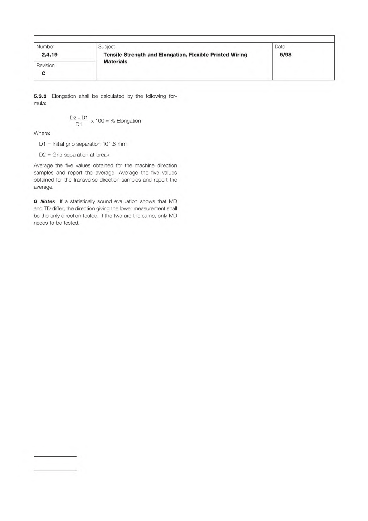
5.3.2
Elongation
shall
be
calculated
by
the
following
for¬
mula:
D2
~
D1
T
cc
0/
i—
I
.•
—
—
—
x
1
00
=
%
Elongation
Where:
D1
二
Initial
grip
separation
101
.6
mm
D2
=
Grip
separation
at
break
Average
the
five
values
obtained
for
the
machine
direction
samples
and
report
the
average.
Average
the
five
values
obtained
for
the
transverse
direction
samples
and
report
the
average.
6
Notes
If
a
statistically
sound
evaluation
shows
that
MD
and
TD
differ,
the
direction
giving
the
lower
measurement
shall
be
the
only
direction
tested.
If
the
two
are
the
same,
only
MD
needs
to
be
tested.
1 Scope
This test method is to determine the land bond
strength of unsupported holes, after repeated soldering and
unsoldering, by mechanical pull in the perpendicular plane.
2 Applicable Documents
Generic Standard on Printed Board Design
3 Test Specimen
Any unsupported component hole
sample or test coupon ‘‘A’’ or ‘‘A/B’’ described in IPC-2221.
Three holes per sample or test coupon shall be tested.
4 Apparatus or Material
4.1 Soldering Iron
60-watt soldering iron capable of pro-
ducing a tip temperature of 232 °C to 260 °C [450 °F to
500 °F].
4.2 Force Tester
Vertical pull force tester capable of oper-
ating at a speed of 50.0 mm [2.0 in] per minute and measur-
ing up to 9 kg [20 pounds] load.
4.3
Tinned or solder coated copper wire.
5 Procedure
5.1 Preparation
5.1.1
If conductors are connected to the land area, the fol-
lowing procedure is to be followed:
Take a sharp model knife and cut conductor at least 6.0 mm
[0.2 in] away from the land. Place blade of knife on edge of
land area where conductor enters. While holding the blade
down, pull conductor to the land and use knife blade as ful-
crum to break conductor from land without disturbing bond of
the land.
5.1.2
Insert wire so that the portion extending from the sol-
dered side of the circuit may be fitted into the gripping mecha-
nism of a tensile tester. The wires shall have a diameter
between 150 µm and 500 µm [5,906 µin and 19,685 µin] less
than the diameter of the hole. The wires shall not be clinched.
Select suitable wire of sufficient length to connect to gripping
mechanism of bond strength tester.
5.1.3
Insert wire in holes in selected lands and solder to
lands by machine or hand, as applicable. The wire shall not be
clinched.
5.2 Soldering Cycles
5.2.1
The hand soldering and desoldering operation of the
wire shall be performed as follows:
Step 1: Solder wire into lands
Step 2: Remove (desolder) wire from lands
Step 3: Resolder wire into lands
Step 4: Remove (desolder) wire from lands
Step 5: Resolder wire into lands
During the desolder and solder steps, solder every other land
in the row and allow the specimen to cool to room tempera-
ture. Then solder the remaining lands.
5.2.2
During the solder and desoldering steps, the soldering
and/or desoldering iron shall have a tip temperature as follows
(see 6.1):
Method A: 260 °C [500 °F] - Default method
Method B: 315 °C [599 °F]
Method C: 371 °C [700 °F]
5.3 Pull Test
5.3.1
Following the fifth cycle, clamp the test specimen suf-
ficiently in the jaws of the bond tester to assure that the test
specimen is perpendicular to the direction of pull.
5.3.2
Apply a pull at the rate of 50.0 mm per minute [2.0 in
per minute] to the wire on the pattern side of the test speci-
men.
5.3.3
The load must be applied perpendicular to the major
surface of the land. The load shall be applied until failure
occurs or the minimum force as specified by the procurement
documentation is reached. The formula to calculate force for
circular lands is as follows:
4L
π (D2
2
– D1
2
)
3000 Lakeside Drive
Bannockburn, IL 60015-1249
IPC-TM-650
TEST METHODS MANUAL
Number
2.4.21
Subject
Land Bond Strength, Unsupported Component Hole
Date
01/07
Revision
F
Originating Task Group
Rigid Printed Board Performance Task Group
(D-33a)
ASSOCIATION CONNECTING
ELECTRONICS INDUSTRIES
®
IPC-2221
Material
/n
this
Test
Methods
Manual
was
voluntarily
established
by
Technical
Committees
of
I
PC.
This
material
/s
advisory
only
and
"s
use
or
adaptation
,
s
entirely
voluntary.
IPC
disclaims
all
liability
of
any
kind
as
to
the
use,
application,
or
adaptation
of
this
material.
Users
are
also
wholly
responsible
for
protecting
themselves
against
all
claims
or
liabilities
for
patent
infringement.
Equipment
referenced
/s
for
the
convenience
of
the
user
and
does
not
imply
endorsement
by
IPC.
Page
1
of
2