IPC-TM-650 EN 2022 试验方法--.pdf - 第307页
IPC -TR- 483 Figure 1 All dimensions are in inches. Four measurements are required as indicated. Locate measuring points approximately 12. 7mm [0.500 in] from each edge in th e fill direc tion, and 2 5.4 mm [1.00 in] from…

Table 2 Initial Stackweight (Wo, grams) vs. Calculated Initial Thickness (ho, mils)
104 106 108 112 113 116 7628
Wo ho Wo ho Wo ho Wo ho Wo ho Wo ho Wo ho
20 1.03 25 1.28 40 1.95 35 3.13 35 2.97 45 3.82 80 6.71
21 1.10 26 1.35 41 2.02 36 3.24 36 3.09 46 3.94 81 6.73
22 1.16 27 1.41 42 2.08 37 3.36 37 3.21 47 4.06 82 6.85
23 1.23 28 1.48 43 2.15 38 3.48 38 3.32 48 4.17 83 6.97
24 1.29 29 1.54 44 2.21 39 3.60 39 3.44 59 4.29 84 7.08
25 1.36 30 1.61 45 2.28 40 3.71 40 3.56 50 4.41 85 7.20
26 1.43 31 1.68 46 2.34 41 3.83 41 3.67 51 4.52 86 7.32
27 1.49 32 1.74 47 2.41 42 3.95 42 3.79 52 4.64 87 7.44
28 1.56 33 1.81 48 2.47 43 4.07 43 3.91 53 4.76 88 7.55
29 1.62 34 1.87 49 2.54 44 4.18 44 4.03 54 4.88 89 7.67
30 1.69 35 1.94 50 2.60 45 4.30 45 4.14 55 4.99 90 7.79
31 1.75 36 2.00 51 2.67 46 4.42 46 4.26 56 5.11 91 7.91
32 1.82 37 2.07 52 2.73 47 4.54 47 4.38 57 5.23 92 8.02
33 1.88 38 2.13 53 2.80 48 4.65 48 4.50 58 5.35 93 8.14
34 1.95 39 2.20 54 2.86 49 4.77 49 4.61 59 5.46 94 8.26
35 2.01 40 2.26 55 2.93 50 4.89 50 4.73 60 5.58 95 8.38
36 2.08 41 2.33 56 2.99 51 5.01 51 4.85 61 5.70 96 8.49
37 2.14 42 2.39 57 3.06 52 5.12 52 4.97 62 5.82 97 8.61
38 2.21 43 2.46 58 3.13 53 5.24 53 5.08 63 5.95 98 8.73
39 2.27 44 2.52 59 3.19 54 5.36 54 5.20 64 6.05 99 8.85
40 2.34 45 2.59 60 3.26 55 5.48 55 5.32 65 6.17 100 8.96
41 2.40 46 2.65 61 3.32 56 5.59 56 5.44 66 6.29 101 9.08
42 2.47 47 2.72 62 3.39 57 5.71 57 5.55 67 6.40 102 9.20
43 2.53 58 2.78 63 3.45 58 5.83 58 5.67 68 6.52 103 9.32
44 2.60 59 2.85 64 3.52 59 5.95 59 5.79 69 6.64 104 9.43
45 2.66 50 2.91 65 3.58 60 6.06 60 5.91 70 6.76 105 9.55
Wo = grams, ho = mils; (n) for 104, 106, 108 = 18; (n) for 112, 113, 116 7628 = 10
Reference Documents
1. Journal of Elastomers and Plastics, 10,367 (1978), C.J. Bartlett
2. Journal of Elastomers and Plastics, 10,365 (1978) D.P. Bloechle
3. IPC-TP-281, The Use of Scaled Flow Testing for B-Stage Prepreg, C.J. Bartlett, D.P. Bloechle, W.A. Mazeika
4. IPC-TP-418, Application of Scaled Flow Testing as an Incoming Inspection Criteria, H.J. Brown
5. IPC-TP-420, Scaled Flow for Testing CRC Prepreg, J. Del, P. Marx, J. Sallo
6. D.P. Bloechle, ‘‘Epoxy Prepreg Characterization using Scaled Flow Testing Techniques,’’ Circuit World, 9,1 (1982), p.8
IPC-TM-650
Number
Subject Date
Revision
Page 3 of 3
2.4.38
Prepreg
Scaled
Flow
Testing
6/91
A
IPC-TR-483
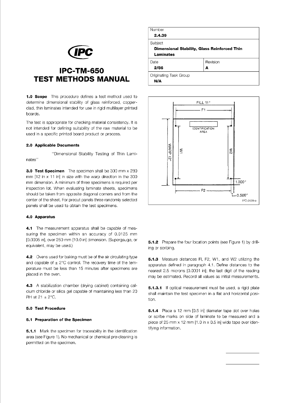
Figure 1 All dimensions are in inches. Four
measurements are required as indicated. Locate
measuring points approximately 12.7mm [0.500 in] from
each edge in the fill direction, and 25.4 mm [1.00 in] from
each edge in the warp direction.
The Institute for Interconnecting and Packaging Electronic Circuits
2215 Sanders Road • Northbrook, IL 60062-6135
Material in this Test Methods Manual was voluntarily established by Technical Committees of the IPC. This material is advisory only
and its use or adaptation is entirely voluntary. IPC disclaims all liability of any kind as to the use, application, or adaptation of this
material. Users are also wholly responsible for protecting themselves against all claims or liabilities for patent infringement.
Equipment referenced is for the convenience of the user and does not imply endorsement by the IPC.
Page 1 of 3
IPC-TM-650
TEST
METHODS
MANUAL
1
.0
Scope
This
procedure
defines
a
test
method
used
to
determine
dimensional
stability
of
glass
reinforced,
copper-
clad,
thin
laminates
intended
for
use
in
rigid
multilayer
printed
boards.
The
test
is
appropriate
for
checking
material
consistency.
It
is
not
intended
for
defining
suitability
of
the
raw
material
to
be
used
in
a
specific
printed
board
product
or
process.
2
.0
Applicable
Documents
1(Dimensional
Stability
Testing
of
Thin
Lami¬
nates'
'
3
.0
Test
Specimen
The
specimen
shall
be
300
mm
x
280
mm
[12
in
x
11
in]
in
size
with
the
warp
direction
in
the
300
mm
dimension.
A
minimum
of
three
specimens
is
required
per
inspection
lot.
When
evaluating
laminate
sheets,
specimens
should
be
taken
from
opposite
diagonal
corners
and
from
the
center
of
the
sheet.
For
precut
panels
three
randomly
selected
panels
shall
be
used
to
obtain
the
test
specimens.
4
.0
Apparatus
4.1
The
measurement
apparatus
shall
be
capable
of
mea¬
suring
the
specimen
within
an
accuracy
of
0.01
25
mm
[0.0005
in],
over
250
mm
[10.0
in]
dimension.
(Supergauge,
or
equivalent,
may
be
used.)
4.2
Ovens
used
for
baking
must
be
of
the
air
circulating
type
and
capable
of
±
2
℃
control.
The
recovery
time
of
the
tem¬
perature
must
be
less
than
15
minutes
after
specimens
are
placed
in
the
oven.
4.3
A
stabilization
chamber
(drying
cabinet)
containing
cal¬
cium
chloride
or
silica
gel
capable
of
maintaining
less
than
20
RH
at
21
±
2
℃.
5
.0
Test
Procedure
5.1
Preparation
of
the
Specimen
5.1.1
Mark
the
specimen
for
traceability
in
the
identification
area
(see
Figure
1).
No
mechanical
or
chemical
pre-cleaning
is
permitted
on
the
specimen.
Number
2.4.39
Subject
Dimensional
Stability,
Glass
Reinforced
Thin
Laminates
Date
Revision
2/86
A
Originating
Task
Group
N/A
FILL
11"
Fl
J
W
F2
t—
0.500"
IPC-2439-a
w
2
IDENTIFICATION
AREA
-
1.000"
5.1.2
Prepare
the
four
location
points
(see
Figure
1)
by
drill¬
ing
or
scribing.
5.1.3
Measure
distances
Fl,
F2,
W1,
and
W2
utilizing
the
apparatus
defined
in
paragraph
4.1
.
Define
distances
to
the
nearest
2.5
microns
[0.0001
in];
the
last
digit
of
the
reading
may
be
estimated.
Record
all
values
as
initial
measurements.
5.
1.3.1
If
optical
measurement
must
be
used,
a
rigid
plate
shall
maintain
the
test
specimen
in
a
flat
and
horizontal
posi¬
tion.
5.1.4
Place
a
12
mm
[0.5
in]
diameter
tape
dot
over
holes
or
scribe
marks
on
side
of
laminate
to
be
measured
and
a
piece
of
25
mm
x
1
2
mm
[1
.0
in
x
0.5
in]
wide
tape
over
iden¬
tifying
information.

IPC-TM-650
MIL-F-14256
The Institute for Interconnecting and Packaging Electronic Circuits
2215 Sanders Road • Northbrook, IL 60062-6135
Material in this Test Methods Manual was voluntarily established by Technical Committees of the IPC. This material is advisory only
and its use or adaptation is entirely voluntary. IPC disclaims all liability of any kind as to the use, application, or adaptation of this
material. Users are also wholly responsible for protecting themselves against all claims or liabilities for patent infringement.
Equipment referenced is for the convenience of the user and does not imply endorsement by the IPC.
Page 1 of 2
IPC-TM-650
TEST
METHODS
MANUAL
1
Scope
This
test
method
is
used
to
determine
the
resis¬
tance
of
laminate
materials
(both
unclad
and
etched
surfaces)
to
the
thermal
abuse
of
a
solder
dip.
Resistance
to
softening,
loss
of
surface
resin,
scorching,
delamination,
blistering
and
measling
are
considered
in
the
evaluation.
2
Applicable
Documents
Test
Methods
Manual
2.4.1
Adhesion,
Tape
Testing
2.4.12
Solderability,
Edge
Dip
Method
Flux
3
Test
Specimen
Each
specimen
must
be
3.18
cm
x
3.18
cm
thickness.
A
separate
specimen
is
required
for
the
unclad,
etched,
fluxed,
and
unfluxed
tests.
Three
samples
are
required
from
each
sheet.
4
Equipment/Apparatus
4.1
An
electrically
heated,
thermostatically
controlled
pot
of
sufficient
size
to
accommodate
the
specimen
and
containing
no
less
than
2.25
kg
of
Sn6O
or
Sn63
4.2
A
device,
as
shown
in
Figure
1
,
or
some
other
similar
device
may
be
used,
if:
•
The
rate
of
immersion,
dwell
time,
and
withdrawal
are
within
the
test
limits
described
in
the
procedure
•
The
specimen
and
solder
surface
remain
perpendicular
within
5
。
•
Wobble,
vibrations,
and
other
extraneous
movements
are
eliminated
4.3
Warnow
2-710
black
acid
resisting
ink,
or
equivalent
4.4
NAZ-
DAR
ER-1
1
1
black
epoxy
ink,
or
equivalent
4.5
A
convection
drying
oven
capable
of
attaining
at
least
149℃
Number
2.4.23
Subject
Soldering
Resistance
of
Laminate
Materials
Date
3/79
Revision
Originating
Task
Group
N/A
5.1
Etched
and
Unetched
Specimen
5.1.1
Expose:
•
One
specimen
having
a
surface
upon
which
no
metal
clad¬
ding
was
ever
applied
•
One
specimen
on
which
the
metal
cladding
has
been
removed
by
standard
etching
processes
•
One
specimen
with
metal
cladding
remaining
to
the
Solder¬
ability
Edge
Dip
Method
in
IPC-TM-650,
Method
2.4.12
5.1.2
Examine
the
specimens
for
evidence
of
discoloration
or
surface
contaminants,
loss
of
surface
resin,
softness,
delamination,
interlaminar
blistering,
or
measles.
The
speci¬
men
having
metal
cladding
must
also
be
examined
for
blister¬
ing
or
delamination
of
the
metal
foil
from
the
laminate
material.
5.2
Plastic
Surface
Tape
Test
5.2.1
Screen
print
one
of
the
test
inks
to
the
surfaces
of
an
unclad
specimen
and
an
etched
specimen.
5.2.2
Treat
test
inks
as
follows:
1
.
Warnow
2-710:
Cure
for
a
minimum
of
30
minutes
in
air
or
oven.
The
dry
film
must
be
hard
and
dull
in
finish.
2.
NAZ-
DAR
ER-1
11
:
Cure
for
a
minimum
of
8
minutes
at
135℃.
The
cured
ink
must
have
a
hard
glossy
finish.
5.2.3
After
the
specimens
have
cured
properly,
perform
the
plating
adhesion
test
on
the
inked
surfaces,
as
defined
in
IPC-
TM-650,
Method
2.4.1
.
Use
type
I
class
A
tape.
5.2.4
Carefully
examine
specimens
for
the
items
discussed
in
5.1.2.
5.2.5
Examine
for
evidence
of
mold
release
agents,
indi¬
cated
by
particles
of
ink
adhering
to
the
tape,
or
by
the
absence
of
ink
from
the
laminate
surface,
or
both.
5
Procedure
5.3
Fluxed
and
Unfluxed
Specimens