IPC-TM-650 EN 2022 试验方法--.pdf - 第318页
IPC-TM-650 Number Subject Date Revision Page 2 of 2 2.4.24.3 Glass Transition Temperature of Organic Films - TMA Method 7/95 6.1 Calibration of the instrument must be carried out according to the manufacturer's reco…
ASTM D 618
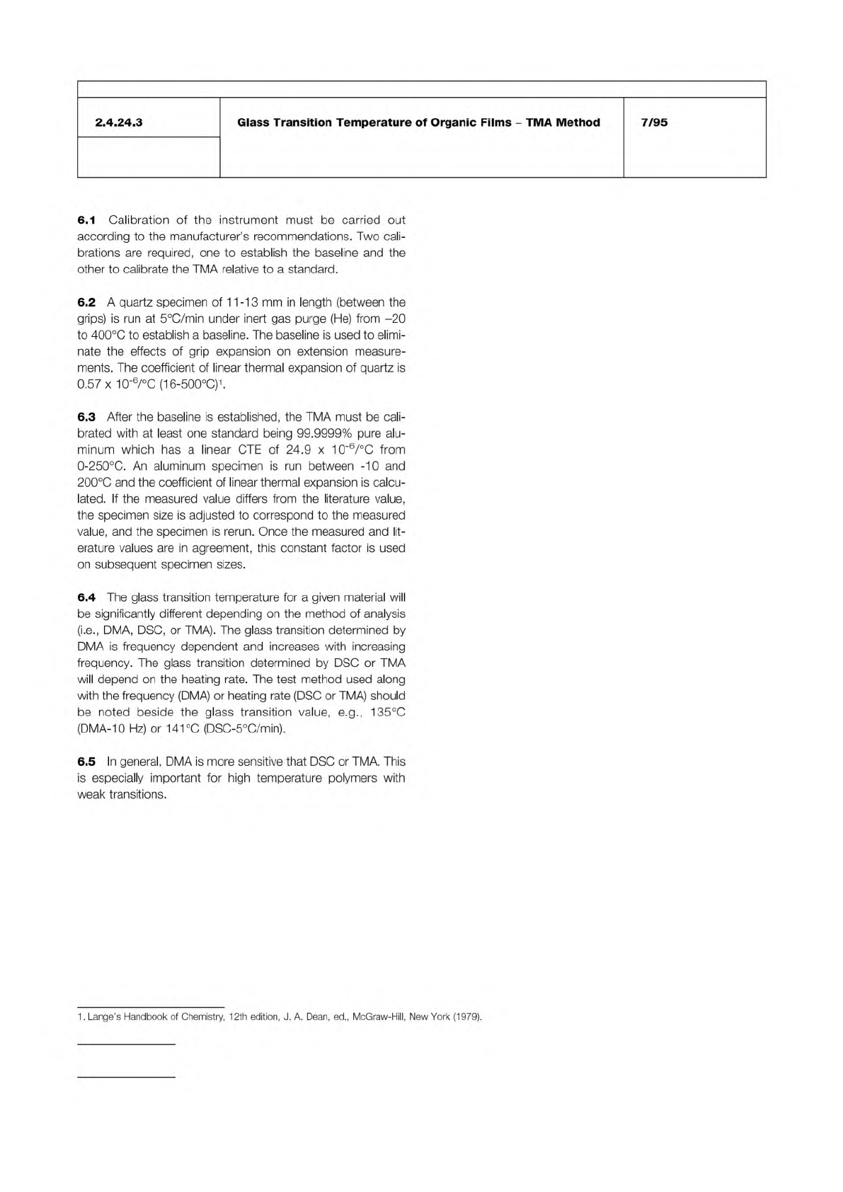
Figure 1
Temperature
Tangent A
Tangent B
T
A
T
B
Extension
The Institute for Interconnecting and Packaging Electronic Circuits
2215 Sanders Road • Northbrook, IL 60062-6135
Material in this Test Methods Manual was voluntarily established by Technical Committees of the IPC. This material is advisory only
and its use or adaptation is entirely voluntary. IPC disclaims all liability of any kind as to the use, application, or adaptation of this
material. Users are also wholly responsible for protecting themselves against all claims or liabilities for patent infringement.
Equipment referenced is for the convenience of the user and does not imply endorsement by the IPC.
Page 1 of 2
IPC-TM-650
TEST
METHODS
MANUAL
1
.0
Scope
This
test
method
establishes
a
procedure
for
determining
the
glass
transition
temperature
of
organic
films
using
thermal
mechanical
analysis
(TMA).
2
.0
Applicable
Documents
Standard
Practice
for
Conditioning
Plastics
and
Electrical
Insulating
Materials
for
Testing
3
.0
Test
Specimen
The
test
specimen
shall
consist
of
a
strip
15-20
mm
long
and
2
mm
wide
with
a
minimum
thick¬
ness
of
10
gm.
4
.0
Apparatus
or
Material
Perkin-Elmer
TMA-7
with
a
film
fixture
in
extension
mode
or
equivalent
equipment
capable
of
handling
films
less
than
25
|im
thick.
5
.0
Procedure
5.1
The
test
specimens
should
be
conditioned
at
23
±
2
℃
and
50
±
5%
relative
humidity
for
not
less
than
24
hours
prior
to
testing.
Refer
to
ASTM
D
618.
5.2
Follow
the
manufacturer's
recommendations
for
equip¬
ment
startup
and
calibration.
5.2
Mount
the
test
specimen
in
the
film
holder.
The
sample
length
(between
the
grips)
should
be
between
11-13
mm.
5.3
Set
the
force
at
30
mN.
5.4
Perform
a
prescan
by
heating
at
a
rate
of
20℃/min
under
inert
atmosphere
from
ambient
to
50℃
beyond
the
apparent
completion
of
the
thermal
activity
to
erase
previous
thermal
history.
5.5
Hold
the
temperature
for
10
min.
5.6
Cool
to
50℃
below
the
transition
temperature
observed
in
the
prescan.
Number
2.4.24.3
Subject
Glass
Transition
Temperature
of
Organic
Films
一
TMA
Method
Date
Revision
7/95
Originating
Task
Group
Deposited
Dielectric
Task
Group
(C-13a)
5.8
Reheat
the
specimen
at
a
rate
of
5
℃/min
until
all
desired
transitions
have
been
completed.
5.9
The
glass
transition
is
determined
by
a
construction
pro¬
cedure
on
the
transition
region
of
the
extension
versus
tem¬
perature
curve
(Figure
1).
5.10
Construct
a
tangent
line
to
the
curve
above
and
below
the
transition.
5.1
1
The
temperature
at
which
the
tangents
intersect
is
the
glass
transition
temperature.
5.12
Report
both
the
glass
transition
(intersection
of
tan¬
gents),
e.g.,
200℃
(TMA-5℃/min),
and
the
temperatures
at
the
beginning
of
tangent
A
(TJ
and
tangent
B
(TB)
(i.e.,
the
transition
range),
e.g.,
transition
range:
1
60-205℃.
6
.0
Notes
5
.7
Hold
the
temperature
for
10
min.
IPC-TM-650
Number
Subject Date
Revision
Page 2 of 2
2.4.24.3
Glass
Transition
Temperature
of
Organic
Films
-
TMA
Method
7/95
6.1
Calibration
of
the
instrument
must
be
carried
out
according
to
the
manufacturer's
recommendations.
Two
cali¬
brations
are
required,
one
to
establish
the
baseline
and
the
other
to
calibrate
the
TMA
relative
to
a
standard.
6.2
A
quartz
specimen
of
1
1-13
mm
in
length
(between
the
grips)
is
run
at
5
℃/min
under
inert
gas
purge
(He)
from
-20
to
400℃
to
establish
a
baseline.
The
baseline
is
used
to
elimi¬
nate
the
effects
of
grip
expansion
on
extension
measure¬
ments.
The
coefficient
of
linear
thermal
expansion
of
quartz
is
0.57
x
10_6/℃
(16-500℃)1.
6.3
After
the
baseline
is
established,
the
TMA
must
be
cali¬
brated
with
at
least
one
standard
being
99.9999%
pure
alu¬
minum
which
has
a
linear
CTE
of
24.9
x
1
0-6/℃
from
0-250℃.
An
aluminum
specimen
is
run
between
-10
and
200℃
and
the
coefficient
of
linear
thermal
expansion
is
calcu¬
lated.
If
the
measured
value
differs
from
the
literature
value,
the
specimen
size
is
adjusted
to
correspond
to
the
measured
value,
and
the
specimen
is
rerun.
Once
the
measured
and
lit¬
erature
values
are
in
agreement,
this
constant
factor
is
used
on
subsequent
specimen
sizes.
6.4
The
glass
transition
temperature
for
a
given
material
will
be
significantly
different
depending
on
the
method
of
analysis
(i.e.,
DMA,
DSC,
or
TMA).
The
glass
transition
determined
by
DMA
is
frequency
dependent
and
increases
with
increasing
frequency.
The
glass
transition
determined
by
DSC
or
TMA
will
depend
on
the
heating
rate.
The
test
method
used
along
with
the
frequency
(DMA)
or
heating
rate
(DSC
or
TMA)
should
be
noted
beside
the
glass
transition
value,
e.g.,
135℃
(DMA-10
Hz)
or
141℃
(DSC-5℃/min).
6.5
In
general,
DMA
is
more
sensitive
that
DSC
or
TMA.
This
is
especially
important
for
high
temperature
polymers
with
weak
transitions.
1
.
Lange's
Handbook
of
Chemistry,
12th
edition,
J.
A.
Dean,
ed.,
McGraw-Hill,
New
York
(1979).
E 1640
D 4065
D 4092
The Institute for Interconnecting and Packaging Electronic Circuits
2215 Sanders Road • Northbrook, IL 60062-6135
Material in this Test Methods Manual was voluntarily established by Technical Committees of the IPC. This material is advisory only
and its use or adaptation is entirely voluntary. IPC disclaims all liability of any kind as to the use, application, or adaptation of this
material. Users are also wholly responsible for protecting themselves against all claims or liabilities for patent infringement.
Equipment referenced is for the convenience of the user and does not imply endorsement by the IPC.
Page 1 of 5
IPC-TM-650
TEST
METHODS
MANUAL
1
Scope
This
test
is
designed
to
determine
the
glass
tran¬
sition
temperature
(Tg)
and
room
temperature
storage
modu¬
lus
(E‘)
of
dielectric
materials
used
in
High
Density
Intercon¬
nect
(HDI)
and
Microvias
by
the
use
of
dynamic
mechanical
analysis
(DMA).
When
testing
a
stand
alone
HDI
dielectric
layer,
DMA
will
pro¬
vide
modulus
as
a
function
of
temperature
and
glass
transition
for
this
layer.
When
DMA
is
used
on
built-up
constructions,
the
data
will
be
a
complex
curve
representing
the
composite
moduli
and
glass
transitions.
Two
methods
are
presented:
•
Method
A
for
thick
specimens
•
Method
B
for
thin
specimens
(recommended
for
HDIS
and
Microvia
dielectric
layers).
For
anisotropic
materials
(reinforced
dielectrics),
the
x
and
y
directions
will
have
different
modulus
vs.
temperature
behav¬
ior.
Anisotropic
materials
shall
be
tested
in
both
the
x
and
y
directions.
2
Applicable
Documents
2.1
ASTM
Documents
Test
Method
for
Assignment
of
the
Glass
Transition
Temperature
by
Dynamic
Mechanical
Analysis
Standard
Practice
for
Determining
and
Reporting
Dynamic
Mechanical
Properties
for
Plastics
Standard
Terminology
Relating
to
Dynamic
Mechani¬
cal
Measurements
on
Plastics
3
Test
Specimen
3.1
Size
Method
A
Flexural
bending
geometry
-
thick
specimens
(>0.5
mm):
Specimens
shall
be
approximately
8
mm
to
12
mm
wide,
20
mm
to
40
mm
long,
and
1
mm
to
2
mm
thick.
The
thickness
shall
be
a
minimum
of
0.5
mm;
for
thicknesses
<0.50
mm,
use
Method
B.
An
aspect
ratio
of
length/thickness
二
10/1
or
greater
should
be
maintained.
Exact
specimen
dimensions
should
be
determined
by
the
apparatus
used.
Number
2.4.24.4
Subject
Glass
Transition
and
Modulus
of
Materials
Used
in
High
Density
Interconnection
(HDI)
and
Microvias
-
DMA
Method
Date
11/98
Revision
Originating
Task
Group
HDI
Test
Methods
Task
Group
(D-42a)
Method
B
Thin
film
tension
geometry
-
thin
specimens
(<0.50
mm):
Specimens
shall
be
approximately
15
mm
to
20
mm
long
and
2
mm
wide.
The
minimum
thickness
is
deter¬
mined
by
the
strength
of
the
material;
it
should
not
break
dur¬
ing
testing.
Exact
specimen
dimensions
may
be
determined
by
the
apparatus
used.
3.2
All
specimens
should
be
fully
cured
according
to
manu¬
facturer's
recommendations.
Thick
specimens
may
be
made
by
use
of
multiple
lamination/cure
cycles
if
required.
3.3
Unless
otherwise
specified,
one
specimen
shall
be
tested,
to
be
taken
from
a
random
location
in
the
material
in
question.
4
Apparatus
or
Material
4.1
A
DMA
capable
of
determination
of
modulus
to
+1%
precision
and
tan
8
resolution
of
0.01
over
the
specified
tem¬
perature
range.
The
DMA
will
preferably
have
computer
data
acquisition
and
analysis.
The
DMA
must
have
an
environmen¬
tal
chamber
capable
of
having
inert
flush
gas
and
capable
of
heating
the
specimen
to
at
least
31
0
℃.
4.2
Diamond
blade
or
saw,
sanding
equipment,
or
equiva¬
lent
to
provide
specimens
of
the
size
and
edge
quality
required
for
Method
A
4.3
Scissors,
razor
blades,
or
equivalent
to
provide
speci¬
mens
of
size
and
edge
quality
for
Method
B
4.4
Air
circulating
oven
capable
of
maintaining
1
05℃
±
2
℃
4.5
Dessicator
capable
of
an
atmosphere
<30%
RH
at
23℃
4.6
Etching
system
capable
of
complete
removal
of
metallic
cladding
5
Procedure
5.1.1
Metallic
clad
specimens
shall
be
tested
without
the
cladding.
Etch
and
dry
using
appropriate procedures
and
equipment.