IPC-TM-650 EN 2022 试验方法--.pdf - 第368页
/ IPC-TM-650 Number Subject Date Revision Page 3 of 3 2.4.41.1 Coefficient of Thermal Expansion by the Vitreous Silica (Quartz) Dilatometer Method 8/97 A where: Lo 二 specimen length (l-o) t = certified expansion of the r…
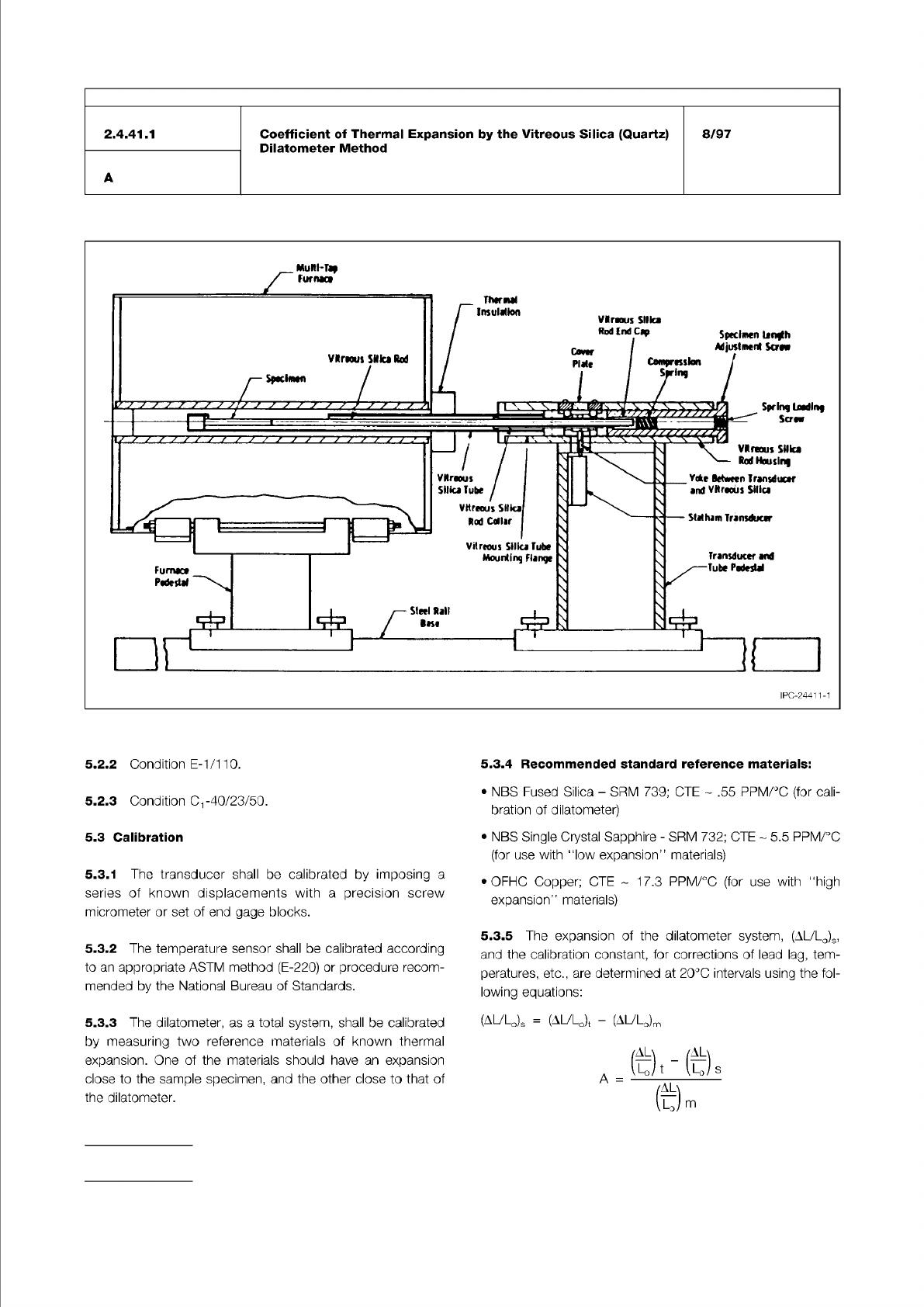
Figure 1 Cutaway view of vitreous silica tube dilatometer
IPC-TM-650
Number
Subject Date
Revision
Page 2 of 3
5.2.2
Condition
E-1/1
10.
5.3.4
Recommended
standard
reference
materials:
5.2.3
Condition
-40/23/50.
5.3
Calibration
5.3.2
The
temperature
sensor
shall
be
calibrated
according
to
an
appropriate
ASTM
method
(E-220)
or
procedure
recom¬
mended
by
the
National
Bureau
of
Standards.
•
OFHC
Copper;
GTE
1
7.3
PPM/℃
(for
use
with
“high
expansion"
materials)
5.3.3
The
dilatometer,
as
a
total
system,
shall
be
calibrated
by
measuring
two
reference
materials
of
known
thermal
expansion.
One
of
the
materials
should
have
an
expansion
close
to
the
sample
specimen,
and
the
other
close
to
that
of
the
dilatometer.
5.3.1
The
transducer
shall
be
calibrated
by
imposing
a
series
of
known
displacements
with
a
precision
screw
micrometer
or
set
of
end
gage
blocks.
•
NBS
Fused
Silica
-
SRM
739;
CTE
.55
PPM/℃
(for
cali¬
bration
of
dilatometer)
5.3.5
The
expansion
of
the
dilatometer
system,
(AL/LO)S,
and
the
calibration
constant,
for
corrections
of
lead
lag,
tem¬
peratures,
etc.,
are
determined
at
20℃
intervals
using
the
fol¬
lowing
equations:
(A^LO)S
=
(AULJ
-
(AULJm
•
NBS
Single
Crystal
Sapphire
-
SRM
732;
CTE
~
5.5
PPM/℃
(for
use
with
l1ow
expansion"
materials)
尚
「代)
s
A
=
2.4.41.1
A
Coefficient
of
Thermal
Expansion
by
the
Vitreous
Silica
(Quartz)
Dilatometer
Method
8/97
给
m
/
IPC-TM-650
Number
Subject Date
Revision
Page 3 of 3
2.4.41.1
Coefficient
of
Thermal
Expansion
by
the
Vitreous
Silica
(Quartz)
Dilatometer
Method
8/97
A
where:
Lo
二
specimen
length
(l-o)
t
=
certified
expansion
of
the
reference
material.
(AULo)m
=
the
measured
expansion
of
the
reference
mate¬
rial.
(
L-o)
s
=
the
expansion
of
the
vitreous
silica
parts
of
the
dila¬
tometer.
5.4
Test
Procedure
Following
the
conditioning
steps
per
5.2,
two
thermal
cycles
shall
be
conducted
per
test.
The
first
is
to
normalize
the
specimen
and
the
second
to
generate
data
for
the
calculation
of
CTE.
5.4.1
Measure
the
initial
length
of
the
specimen,
using
the
micrometer
to
±
.001
inch.
5.4.2
Place
the
specimen
in
the
dilatometer
after
making
certain
that
all
contacting
surfaces
are
free of
foreign
material.
Specimens
with
thickness
0.125
inch
shall
be
supported
with
side
plates.
Care
must
be
taken
to
assure
good
seating
of
the
specimen
against
the
bottom
of
the
tube
bottom
and
the
push
rod.
5.4.3
Place
the
thermocouple
sensor
in
intimate
contact
with
the
specimen
at
midlength.
5:4.4
Mount
the
transducer
to
provide
a
stable
contact
with
the
probe.
The
sample
loading
force
shall
be
the
minimum
necessary
for
proper
contact
between
the
rod
and
specimen,
and
the
bottom
of
the
tube
and
specimen.
Set
the
transducer
at
a
nominal
initial
reading.
5.4.5
Place
the
assembled
dilatometer
into
the
chamber
and
allow
the
temperature
of
the
specimen
to
come
to
equi¬
librium.
5.4.6
Record
the
initial
readings
of
the
thermocouple
and
the
transducer.
5.4.7
Heat
and
cool
at
a
constant
rate
of
2
℃/min.
5.4.8
Record
length
changes
as
a
function
of
temperature.
procedure
per
5.4.1
-5.4.8,
following
the
first
cycle.
Remea¬
surement
of
the
specimen
length
must
not
be
omitted
prior
to
start
of
the
second
cycle.
5.4.10
Test
a
total
of
four
specimens,
two
prepared
with
the
length
in
the
machine
direction
of
the
laminate
reinforcement
and
two
cut
in
the
transverse
direction.
This
quantity
is
intended
to
represent
the
expansion
characteristics
of
a
18
inch
x
24
inch
panel
size.
6.0
Calculations
6.1
Linear
thermal
expansion
(LTE),
the
change
in
length
per
unit
length
resulting
from
a
temperature
change
is
represented
by:
where:
(Sa
is
the
expansion
as
indicated
by
the
transducer,
AL
is
the
observed
change
in
length
(AL
=
L2-LJ.
LTE
is
often
expressed
in
pm/m
(parts
per
million).
6.2
Mean
coefficient
of
linear
thermal
expansion
-
the
linear
thermal
expansion
per
change
in
temperature.
Represented
by:
AL
L
(
8
m
=
=
AT
LSi)
where
and
L2
are
the
lengths
of
the
specimen
at
the
test
temperatures
3
and
T2.
6.3
Instantaneous
coefficient
of
linear
thermal
expansion
-
the
slope
of
the
linear
thermal
expansion
curve
at
temperature
T.
Represented
by:
8
T
工
匹
匚
6.4
Plots
of
the
following
are
commonly
used
as
required:
AL
丁 丁
-
—
vs.
T;
oc
m
vs.
T
l-O
When
reporting
the
mean
coefficient
of
thermal
expansion,
the
temperature
ranges
must
be
specified.
5.4.9
Remove
the
specimen
from
the
fixture
and
repeat
the
Material in this Test Methods Manual was voluntarily established by Technical Committees of IPC. This material is advisory only
and its use or adaptation is entirely voluntary. IPC disclaims all liability of any kind as to the use, application, or adaptation of this
material. Users are also wholly responsible for protecting themselves against all claims or liabilities for patent infringement.
Equipment referenced is for the convenience of the user and does not imply endorsement by IPC.
Page 1 of 4
r
ASSOCIATION
CONNECTING
/
ELECTRONICS
INDUSTRIES
®
221
5
Sanders
Road
Northbrook,
IL
60062-6135
IPC-TM-650
TEST
METHODS
MANUAL
1
Scope
To
describe
the
strain
gage
method
for
determin¬
ing
linear
thermal
expansion
of
laminated
materials
within
the
temperature
range
of
-55
to
+130
and
inorganic
sub¬
strates
(nonlaminated)
with
a
range
of
-55
to
+150
℃
.
1.1
Care
should
be
taken
if
the
higher
temperatures
are
used.
The
adhesive
shown
is
rated
by
the
manufacturer
from
less
than
-200
to
greater
than
+300
℃
;
however,
for
higher
temperature
pretesting
with
the
Titanium
Silicate
Stan¬
dard
or
materials
of
known
thermal
expansion
characteristics
is
recommended.
2
Applicable
Documents
None
3
Test
Specimens
3.1
Specimens
are
normally
flat
pieces
of
laminate
or
printed
wiring
boards/assemblies
that
are
to
be
tested
nondestruc-
tively.
Dimensions
are
to
be
50.0
mm
x
50.0
mm
[2.0
in
X
2.0
in]
minimum
by
1.5
mm
[0.060
in]
minimum
thick.
Plated-through
holes
in
the
specimen
are
not
desirable,
but
can
be
tolerated
to
a
certain
extent.
If
possible,
the
strain
gages
are
to
be
located
as
far
from
the
PTHs
as
possible
and
centered
with
regard
to
surrounding
PTHs.
Mounting
strain
gages
over
PTHs
will
result
in
measurements
that
may
not
be
representative
of
the
sample
material.
For
each
material
or
lot
tested,
a
minimum
of
three
determi¬
nations
shall
be
made
in
each
of
the
x
and
y
directions.
4
Apparatus
4.1
Silicon
carbide
paper,
220,
320
and
400
grit
4.2
Cotton
tipped
applicator
4.3
Tweezers,
stainless
steel,
Style
3c
4.4
Scissors,
stainless
steel,
2
to
4
inch
blades
4.5
Tape,
Mylar,
transparent,
1/2
inch
wide
4.6
Tape,
Mylar,
transparent
1
inch
4.7
Tape,
PFTE,
1
inch
wide,
no
adhesive
Number
2.4.41.2
Subject
Coefficient
of
Thermal
Expansion
—
Strain
Gage
Method
Date
Revision
05/04
A
Originating
Task
Group
Rigid
Printed
Board
Performance
Task
Group
(D-33a)
4.9
Binder
clips,
No.
20,
small
4.10
Silicone
gum
pad
(2.5
mm
[0.0984
in]
thick)
with
metal
backup
plate
4.11
Test
plate
constructed
of
1.25
mm
[0.050
in]
thick
Alloy
42
plated
with
0.025
mm
[0.001
in]
of
copper
4.12
M-Prep
Conditioner
A
or
equivalent
4.13
M-Bond
610
Adhesive
or
equivalent
(M-Bond
600
for
lower
cure
temperatures,
if
applicable)
4.14
M-Prep
Neutralizer
5
or
equivalent
4.15
M-Coat
B,
Nitrile
rubber
coating
4.16
Cleaning
solvent,
Isopropan
OL
or
equivalent
4.17
Strain
gages,
Type
WK-06-250BG,
Measurements
Group
Inc.
(Other
strain
gages
may
be
selected
for
customiz¬
ing
for
a
specific
material
or
temperature
range.)
4.18
Alloy
42
Holding
Fixture
(-30-400
℃
)
=
4.5-5.0
ppm/℃
4.19
Solder
terminals,
Type
CEG-63S,
Measurements
Group
Inc.
(Terminal
may
be
integral
when
using
WK
series
strain
gage
with
option
W.)
4.20
Select
a
solder
that
will
maintain
a
connection
at
test
temperature;
Solder
Sn-63/Pb-37
Liquidus
=
183
[361
°F]
Solder
Sn-96.5/Ag-3.5
Liquidus
二
221
[430
°F]
Solder
Pb-97.5/Ag-1
.5/Sn-1
Liquidus
=
309
[588
°F]
4.21
Solder
Flux,
Type
RMA
or
equivalent
4.22
Soldering
Iron,
1
5
to
25
watt
4.23
M-line
Rosin
Solvent,
Measurements
Group
Inc.
4.24
Oven
for
Curing
M-Bond
Adhesive
with
heat
rise
of
3
to
1
1
℃
/min
[5
°F
to
20
°F/min].
4.8
Binder
clips,
No.
100,
large
4.25
Gauze
Sponge