IPC-TM-650 EN 2022 试验方法--.pdf - 第379页
IPC-TM-650 Number Subject Date Revision Page 2 of 3 2.4.43 Solder Paste ― Solder Ball Test 1/95 5.2.3.2 Place the substrate on the hot plate. As soon as the solder has melted, withdraw the substrate from the hot plate ma…
The Institute for Interconnecting and Packaging Electronic Circuits
2215 Sanders Road • Northbrook, IL 60062-6135
Material in this Test Methods Manual was voluntarily established by Technical Committees of the IPC. This material is advisory only
and its use or adaptation is entirely voluntary. IPC disclaims all liability of any kind as to the use, application, or adaptation of this
material. Users are also wholly responsible for protecting themselves against all claims or liabilities for patent infringement.
Equipment referenced is for the convenience of the user and does not imply endorsement by the IPC.
Page 1 of 3
IPC-TM-650
TEST
METHODS
MANUAL
1
.0
Scope
This
test
is
carried
out
to
determine
the
reflow
properties
of
the
solder
paste.
The
ability
of
the
prealloyed
solder
particles
in
the
paste
to
reflow
into
a
sphere
on
a
non¬
wettable
substrate
is
determined
under
defined
test
condi¬
tions.
2
.0
Applicable
Documents
None
3
.0
Test
Specimen
Frosted
glass
microscope
slide,
alu¬
mina
substrate
or
glass/epoxy
printed
circuit
board
with
a
thickness
of
0.60
to
0.80
mm
and
a
minimum
length
and
width
dimension
of
76
mm
and
25
mm,
respectively.
4
.0
Equipment/Apparatus
4.1
Metal
Stencils
4.1.1
Stencil
for
Type
1-4
Stencil
76
mm
x
25
mm
x
0.2
mm
provided
with
at
least
3
round
holes
of
6.5
mm
diameter
apertures
with
a
minimum
distance
between
centers
of
10
mm.
4.1.2
Stencil
for
Type
5-6
Stencil
76
mm
x
25
mm
x
0.1
mm
provided
with
at
least
3
round
holes
of
1
.5
mm
diameter
apertures
with
a
minimum
distance
between
centers
of
10
mm.
4.2
Spatula
4.3
Solder
bath
not
less
than
100
mm
x
100
mm
x
75
mm
deep
containing
solder
suitable
to
maintain
a
temperature
of
25℃
above
the
liquidus
temperature
of
the
solder
paste
being
evaluated.
4.4
Flat
hot
plate
4.5
Surface
temperature
thermometer
4.6
Magnifying
glass
with
a
1
0
to
20
times
magnification.
5
.0
Procedure
5.1
Preparation
Number
2.4.43
Subject
Solder
Paste
~~
Solder
Bal
1
Test
Date
1/95
Revision
Originating
Task
Group
Solder
Paste
Task
Group
(5-24b)
5.1.1
Set
the
temperature
of
the
solder
bath
or
hot
plate
at
a
temperature
of
25℃
+/-3℃
above
the
liquidus
temperature
of
the
solder
alloy.
5.1.2
Homogenize
the
solder
paste
by
hand
stirring
with
a
spatula.
5.1.3
Condition
the
paste
to
uniform
temperature
of
25°
C
+/-2℃.
5.1.4
Prepare
two
test
specimens
with
either/or
both
sten¬
cils
listed
above
(4.1
.1
and
4.1
.2).
The
solder
paste
should
be
squeeged
with
the
spatula
to
fill
and
level
each
hole.
5.2
Test
5.2.1
Test
Conditions
5.2.
1.1
Test
one
specimen
within
15
+/-5
minutes
after
placement
of
solder
paste
on
test
coupon.
5.2.1.
2
Test
the
second
specimen
4
hours
+/-15
minutes
after
placement
of
solder
paste
on
test
coupon.
Storage
for
4
hours
shall
be
at
25℃
+/-3℃
and
50
+/-1
0%
RH.
5.2.2
Conditioning
Heating
Equipment
5.2.2.
1
Clean
the
surface
of
the
solder
bath
with
the
scraper.
5.2.2.2
Remove
all
foreign
material
from
the
surface
of
the
hot
plate
to
ensure
proper
control.
5.2.3
Solder
Reflow
Reflow
specimens
by
one
of
the
fol¬
lowing
two
methods.
5.2.3.
1
Lower
the
substrate,
in
a
horizontal
position
with
the
paste
deposit
on
top,
into
the
solder
bath
at
a
speed
of
25
+/-
2
mm/second
until
the
substrate
is
50%
submerged.
It
is
important
that
good
thermal
contact
is
achieved
between
the
molten
solder
and
the
substrate.
As
soon
as
the
solder
has
melted,
withdraw
the
substrate
from
the
solder
bath
maintain¬
ing
it
in
a
horizontal
position.
The
total
time
on
the
solder
bath
shall
not
exceed
20
seconds.
IPC-TM-650
Number
Subject Date
Revision
Page 2 of 3
2.4.43
Solder
Paste
―
Solder
Ball
Test
1/95
5.2.3.2
Place
the
substrate
on
the
hot
plate.
As
soon
as
the
solder
has
melted,
withdraw
the
substrate
from
the
hot
plate
maintaining
a
horizontal
position.
The
reflow
shall
occur
within
20
seconds
after
the
specimen
is
placed
in
contact
with
the
hot
plate.
5.3
Evaluation
5.3.1
Examine
the
reflowed
specimens
under
10X
to
20X
magnification.
5.3.2
Solder
ball
size
and
number
should
be
compared
with
Figure
1
.
5.3.3
Record
the
degree
of
reflow
in
comparison
with
Figure
1
for
the
6.5
cm
and
1
.5
cm
acceptance/reject
conditions,
respectively.
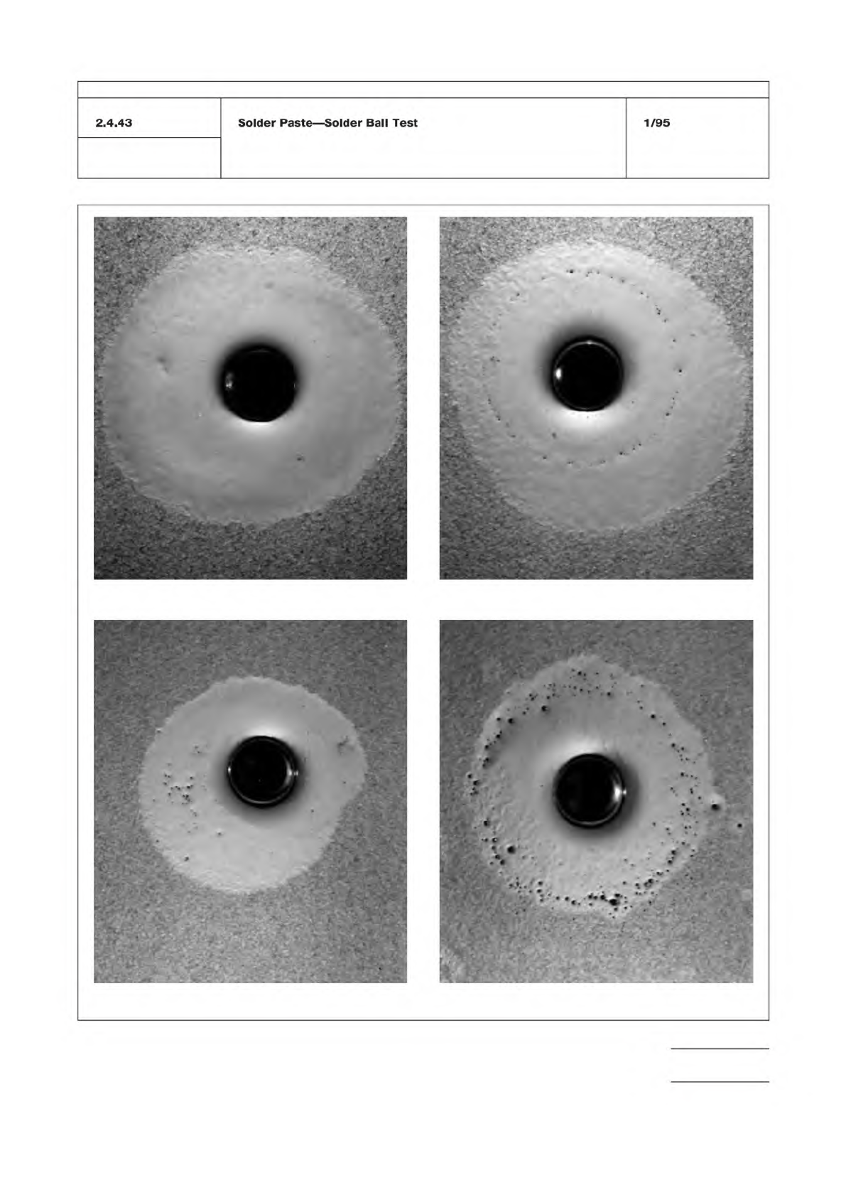
Figure 1 Solder ball test standards
Preferred Acceptable
Unacceptable; Clusters Unacceptable
IPC-TM-650
Number
Subject Date
Revision
Page 3 of 3
2.4.43
Solder
Paste
―
Solder
Ball
Test
1/95