IPC-TM-650 EN 2022 试验方法--.pdf - 第421页
5.2.1.1 Establish ing the Electrical Length of the Mea- surement Sy stem To assist in tracking the repeatabilit y and suitability of the measurement sys tem, the method includes the following proce dure to determine the …
5.1.2 Pre-Measurement Checks
5.1.2.1 Instrument Warm-Up and Stability
Before per-
forming delay measurements, the user
ensure adequate
instrument warm-up time as specified by the instrument
manufacturers, and ensure that the TDR waveform is not drift-
ing in amplitude or time.
5.1.2.2 Environmental Conditions
The user ensure
that the temperature and humidity of the test environment is
within TDR instrument specifications and that the conditions
will be stable for the duration of the measurements. If the test
environment is substantially different than that used for speci-
men conditioning (see 3.3), the user document this in
the test reports.
5.1.2.3 Test Structure Isolation
The user ensure
that the signal line and reference planes of the test structures
are located an adequate distance from objects and surfaces
(such as the work surface of a test bench) that could electri-
cally couple or interact with the test structure and probes. If
surface layer microstrip lines are used, the recommendation is
to keep extraneous objects and surfaces at least 6 w from the
test coupon or PB, were w is the width of the signal line. If the
tests are being conducted with hand probes, care must be
taken to ensure that the hands and arms of the operator do
not come in close proximity to the coupon or PB being tested.
Any fixtures used to ensure electrical isolation of the test fix-
tures must also be sufficiently strong to accommodate the
probing force required for repeatable electrical connections.
5.1.3 Suitable Waveform Epochs
The waveform epoch is
the measurement interval over which the propagation time for
a given discontinuity will be computed. The time epoch may
be described in terms of the TDR instrument parameters delay
and time per division. The user
ensure that the instru-
ment settings can be adjusted so the waveform epochs can
contain the arrival of the far end reflection signals of both the
shorter line and the longer line in the test structure; the user
must ensure an epoch includes the reflection signal and suffi-
cient pre- and post-waveform data to establish the required
reference amplitude levels; and the user
ensure that the
delay and time/div settings can re-adjusted to repeat the
desired epochs. This requires probing both test structures
using the TDR measurement set-up (similar to that depicted in
Figure 5-1). As shown in Figure 5-1, the user may first find the
arrival point of the reflection signal for the open-circuit probe
to help locate the subsequent reflection signal of the intercon-
nection test structure.
5.1.4 Suitable Amplitude Resolution
In order to com-
pute propagation delay, this method requires the recording of
the instants when the TDR waveform crosses a specified volt-
age reference level. The reference level, V
REF
, is given gener-
ally by:
V
REF
= xV
refl
+ V
off,refl
where V
refi
is the amplitude of the reflected pulse (measured
when it is superimposed on an incident step pulse), x is the
fraction of V
refl
used to determine the transition instant (for
example, x = 0.5 corresponds to the 50% reflection amplitude
value), and V
off, refl
is the amplitude of an incident TDR step
pulse.
This method specifies two possible values for x:
x
5%
= 0.05
x
50%
= 0.50
The method also allows the user to specify their own x as long
as the same value of x is used in all delay measurements and
verification field tests. The user must document which value of
x is used in the test reports.
The user
ensure that the TDR equipment amplitude set-
tings can be adjusted to capture the reference level V
REF
with
sufficient resolution to minimize errors in recording time of the
crossing instant.
5.2 Propagation Delay TDR Measurement Procedures
This section contains the methods for measuring the propa-
gation delay of single-ended transmission lines. The following
steps should be used when the interconnect test structures
under test are unbalanced (single-ended) transmission lines.
This process can be followed or automated (recommended).
Additionally, the use of quality fixtures based or robotic prob-
ing systems may reduce probe placement uncertainty com-
pared to hand probe techniques of certain users.
5.2.1 Multiple Line Method
To mitigate the effects of
imperfect measurement system cables, probes, and contact
pad discontinuities, the propagation delay measurements are
defined using the ratio of differences of two measurements
made on separate lines that are very similar except for their
physical length. Therefore, the procedure requires careful and
repeatable connections and measurements of TDR waveform
from two lines of the interconnection test structure.
Number
2.5.5.11
Subject
Propagation Delay of Lines on Printed Boards by TDR
Date
04/2009
Revision
IPC-TM-650
shall
shall
shall
shall
shall
shall
Page
9
of
16
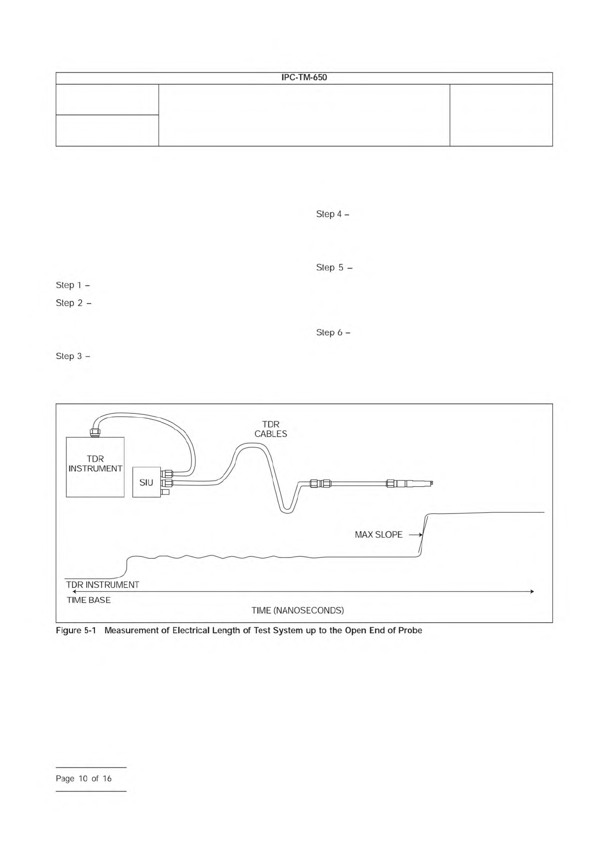
5.2.1.1 Establishing the Electrical Length of the Mea-
surement System
To assist in tracking the repeatability and
suitability of the measurement system, the method includes
the following procedure to determine the electrical length of
the TDR measurement system from the TDR sampler to the
end of the probe tip. The user may record this time value for
a given set-up over subsequent measurement sessions in
order to verify consistency in system performance over long
time periods.
Turn on the TDR source and enable triggering.
Hold the probe in the air away from other objects
and surfaces and set the waveform epoch to include both the
incident signal from the TDR source and the superimposed
reflection signal from the probe tip (see Figure 5-1).
For this epoch, adjust the number of sample points
to achieve a sample density of no less than 2 S/ps. For
example, this is achieved with a time record of 4,000 sample
points and a waveform epoch that is 2,000 ps long (10 divi-
sion x 200 ps/div).
Identify the arrival time t
inc
of the incident pulse edge
as 50% of the incident amplitude. For step signals, use the
difference of average pre- and post-step voltage levels to
establish the incident amplitude.
Identify the arrival time t
refl
of the reflection pulse
edge as 50% of the reflection amplitude. For step signals, use
the difference of average pre- and post-step voltage levels to
establish the reflection amplitude (this is often near the region
of maximum dV/dt.)
Record the system’s electrical length as one half of
the round-trip time: t
syslen
= (t
ref
- t
inc
)/2.
IPC-25511-5-1
(Note: The optional static isolation unit (SIU) is a protection device designed to eliminate static discharge damage to the TDR sampling
head.)
Number
2.5.5.11
Subject
Propagation Delay of Lines on Printed Boards by TDR
Date
04/2009
Revision
IPC-TM-650
Step
1
-
Step
2
-
Step
3
-
Step
4
-
Step
5
-
Step
6
-
Page
10
of
16
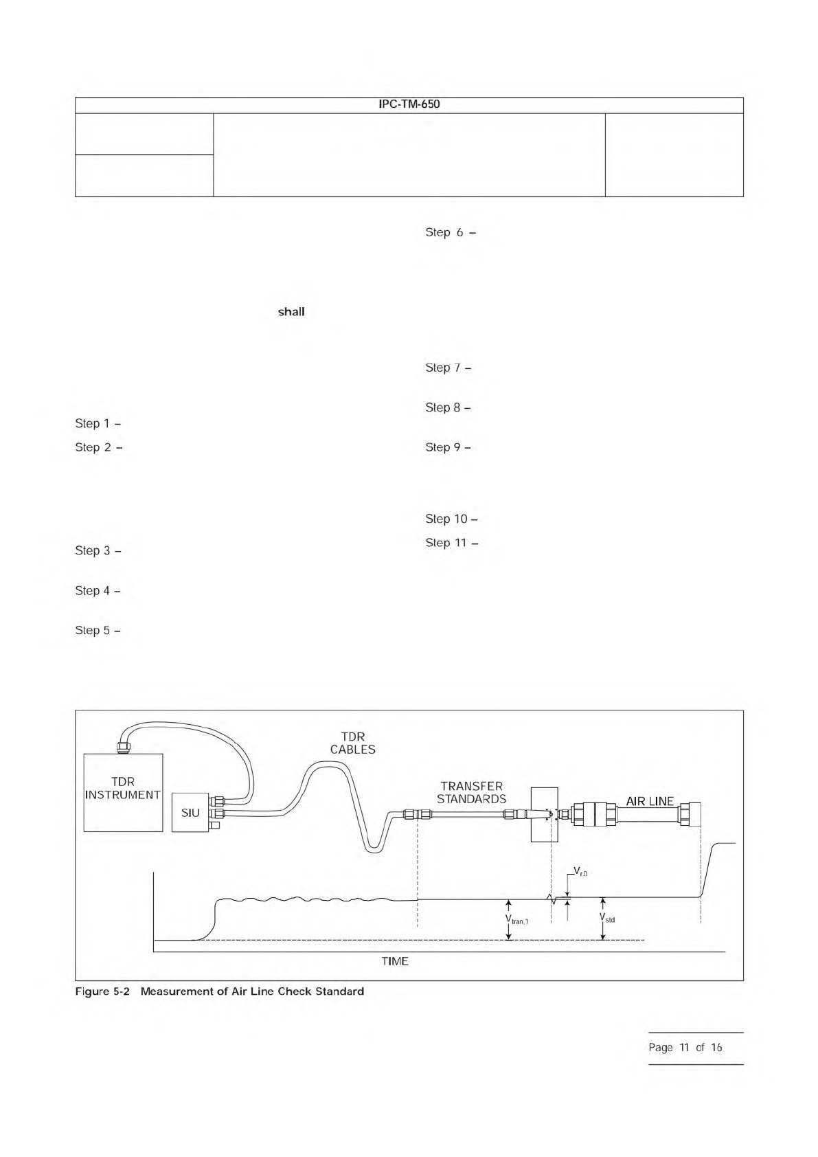
5.2.1.2 Verification Field Check
The method includes a
verification procedure to test the success of the measurement
set-up in determining propagation delay. The verification pro-
cedure follows the same steps used when characterizing test
specimens, but uses known and precise delay verification ele-
ments (as described in 4.3.7.) The user
perform this field
check prior to reporting delay results from the test specimens.
The user must fabricate their own transition cards that allow
electrical connection to the end of the coaxial air lines using
the probes of the measurement set-up. Figure 5-2 shows the
probe contacting a transition to coaxial adapter.
Turn on the TDR source and enable triggering.
Connect the probe-to-coax adapter to one end of
the longer air line check standard, leaving the opposite end
open circuit. For beadless air lines, this requires the addition
of an open circuit coax adapter at the far end in order to hold
the center conductor in place. As with all coax connections,
use the appropriate connection torque (see 4.3.1).
Connect the probe to the contact pads of the tran-
sition adapter.
Adjust the waveform epoch to capture the reflection
signal from the far end of the longer open circuit air line.
Measure the arrival time of the reflection signal from
the open circuit by testing when the reflection signal crosses
V
REF
as defined above for the user-selected value of x. Record
the arrival time value as t
T1
.
Connect the same probe-to-coax adapter used
above in Step 2 to one end of the shorter air line check stan-
dard, leaving the opposite end open circuit. For beadless air
lines, this requires the addition of an open circuit coax adapter
at the far end in order to hold the center conductor in place.
Use the same open circuit coax adapter used in Step 2. As
with all coax connections, use the appropriate connection
torque (see 4.3.1).
Connect the probe to the contact pads of the tran-
sition adapter.
Adjust the waveform epoch to capture the reflection
signal from the far end of the shorter open circuit air line.
Measure the arrival time of the reflection signal from
the open circuit by testing when the reflection signal crosses
V
REF
as defined above for the user-selected value of x. Record
the arrival time value as t
T2
.
Calculate the propagation time t
p
= t
T1
- t
T2
.
Compare t
p
to the difference in delay values pro-
vided by the air line manufacturer or calibration lab, and test
whether or not the measurement system t
p
agrees with the
standards to within the uncertainty target of the measurement
system or desired uncertainty required by the test specimens.
The propagation time will not be known to contain a better
resolution than that established in 4.1.2.
IPC-25511-5-2
Number
2.5.5.11
Subject
Propagation Delay of Lines on Printed Boards by TDR
Date
04/2009
Revision
SIU
TIME
TDR
INSTRUMENT
Step
1
-
Step
2
-
Step
3
-
Step
4
-
Step
5
-
Step
6
-
Step
7
-
Step
8
-
Step
9
-
Step
10
-
Step
11
-
Figure
5-2
Measurement
of
Air
Line
Check
Standard
IPC-TM-650
—
Page
11
of
16