IPC-TM-650 EN 2022 试验方法--.pdf - 第439页
Equipment drif t may occur as a function of time and environment; check with equipment manufacturer for proper calibration frequency. 4.2 EBW , RIE, and SET2D IL Apparatus EBW, R IE, and SET2DIL utilize a TDR m easuremen…
IPC-TM-650
Page 6 of 25
Number
2.5.5.5
Subject
Stripline
Test
for
Permittivity
and
Loss
Tangent
(Dielectric
Constant
and
Dissipation
Factor)
at
X-Band
Date
3/98
Revision
C
be
taken
to
assure
that
power
is
continuously
supplied
to
this
unit
to
avoid
a
longer
warm-up
time.
Other
equipment
using
vacuum
tube
devices
will
require
a
longer
warm-up
time
as
specified
in
the
manufacturer's
literature.
The
temperature
of
the
test
fixture
shall
be
in
the
range
of
22℃
to
24℃,
unless
otherwise
specified.
If
this
standard
temperature
is
to
be
used
and
the
temperature
of
the
fixture
is
to
be
controlled
by
the
ambient
conditions
in
the
testing
laboratory,
then
the
laboratory
shall
be
maintained
at
22℃
to
24℃
and
the
fixture
shall
be
stored
in
the
laboratory
for
at
least
24
hours
prior
to
use.
If
non-standard
temperature
is
specified
and
the
fixture
of
4.1
is
used
with
the
temperature
control
apparatus
described
in
4.2,
then
the
rest
of
this
paragraph
applies.
Prior
to
making
electrical
measurements,
the
circulator
is
started
and
adjusted
to
within
1
℃
of
the
desired
test
temperature.
The
time
required
for
stabilization
depends
on
the
specific
temperature
control
apparatus
in
use,
the
size
of
the
circulation
bath
tank,
and
the
temperature
selected.
Additional
stabilization
time
will
be
required
for
each
specimen
to
come
to
the
set
temperature
after
it
has
been
clamped
in
the
fixture.
The
test
fixture
containing
the
test
specimens
shall
be
placed
in
the
clamping
fixture
and
the
specified
force
of
4.45
土
0.22
kN
is
applied
through
the
calibrated
force
gauge
to
the
1290
mm2
area
centered
directly
over
the
resonant
circuit
as
shown
in
the
assembly
of
Figure
12,
Figure
13,
or
Figure
15.
6.2
Manual
Measurement
of
the
Specimen
The
follow¬
ing
procedure
is
applicable
where
equipment
as
described
in
4.1
is
available.
The
equipment
of
4.2
could
also
be
operated
manually.
The
stripline
resonator
formed
by
the
fixture
pattern
card
and
ground
planes
with
the
specimen
cards
inserted
is
referred
to
as
a
cavity.
The
sweep
oscillator
is
referred
to
here
as
the
sweeper.
6.2.1
Determination
of
Cavity
Resonant
Frequency
The
resonant
frequency
of
the
circuit
shall
be
found
by
scanning
the
sweeper
over
the
expected
transmission
range
of
the
test
resonator.
The
sweeper
shall
be
precisely
adjusted
to
the
fre¬
quency
that
produces
a
maximum
reading
of
the
SWR
Meter
No.
1
.
The
frequency
meter
shall
then
be
adjusted
for
a
mini¬
mum
reading
of
the
SWR
Meter
No.
2.
Record
the
resonant
frequency.
The
input
selector
of
the
SWR
Meter
No.
1
should
be
set
for
low
impedance
input
for
proper
square
law
detec¬
tion.
6.2.2
Determination
of
Cavity
Half-Power
Points
With
the
incident
signal
having
been
set
to
maximum
resonator
transmission,
adjust
the
gain
of
the
SWR
Meter
No.
1
until
the
meter
reads
0
dB.
The
frequency
of
the
sweeper
shall
then
be
adjusted
to
give
3
dB
readings
both
above
and
below
the
maximum
transmission
frequency.
Measure
each
frequency
with
the
frequency
meter
and
record
the
results:
•
f1:
above
the
maximum
transmission
frequency
•
f2:
below
the
maximum
transmission
frequency
6.3
Automated
Measurement
of
the
Specimen
For
an
automated
system
to
be
used
in
performing
the
measure¬
ment,
computer
software
is
needed
that
will
collect
paired
values
of
frequency
and
transmitted
power.
From
this
data,
the
frequency
for
maximum
power
transmission
and
the
fre¬
quencies
of
the
half
power
points
are
determined.
The
com¬
puter
program
may
optionally
include
computation
of
permit¬
tivity
and
loss
tangent
as
described
in
7.0.
Results
and
collected
data
may
be
displayed
on
the
screen,
stored
in
a
disk
file,
sent
to
a
printer,
or
any
combination
of
these.
In
one
possible
mode
of
operation
with
the
equipment
described
in
4.2,
the
following
sequence
of
steps
is
performed
as
many
times
as
necessary
to
get
enough
data
to
complete
the
test
procedure.
The
computer
is
designated
as
the
con¬
troller
on
the
GPIB.
6.3.1
The
computer
sets
the
sweeper
to
a
selected
carrier
wave
frequency
without
an
AM
or
FM
audio
signal
to
a
desired
output
power
level,
such
as
10
dBm.
6.3.2
The
same
frequency
is
given
to
the
synchronizer
with
instructions
to
lock
the
frequency
of
the
sweeper
to
the
speci¬
fied
value.
6.3.3
The
computer
checks
the
synchronizer
for
status
until
the
status
value
drops
to
zero,
indicating
the
frequency
is
locked.
6.3.4
The
power
meter
reading
is
obtained
by
the
computer.
Since
it
takes
a
finite
amount
of
time
for
the
power
sensor
to
stabilize,
either
a
delay
is
used
or
the
reading
may
be
taken
repeatedly
until
consecutive
readings
meet
a
given
require¬
ment
for
stability.
6.4
Use
of
the
Network
Analyzer
for
Measurement
of
the
Specimen
An
automated
network
analyzer
may
be
used
either
by
operating
the
front
panel
controls
manually
or
under
computer
control
with
suitable
specialized
software.
The
fixture
with
the
specimen
is
connected
by
test
cables
and
adapters
as
a
device
under
test.
Set
up
the
instrument
so
the
Equipment drift may occur as a function of time and
environment; check with equipment manufacturer for proper
calibration frequency.
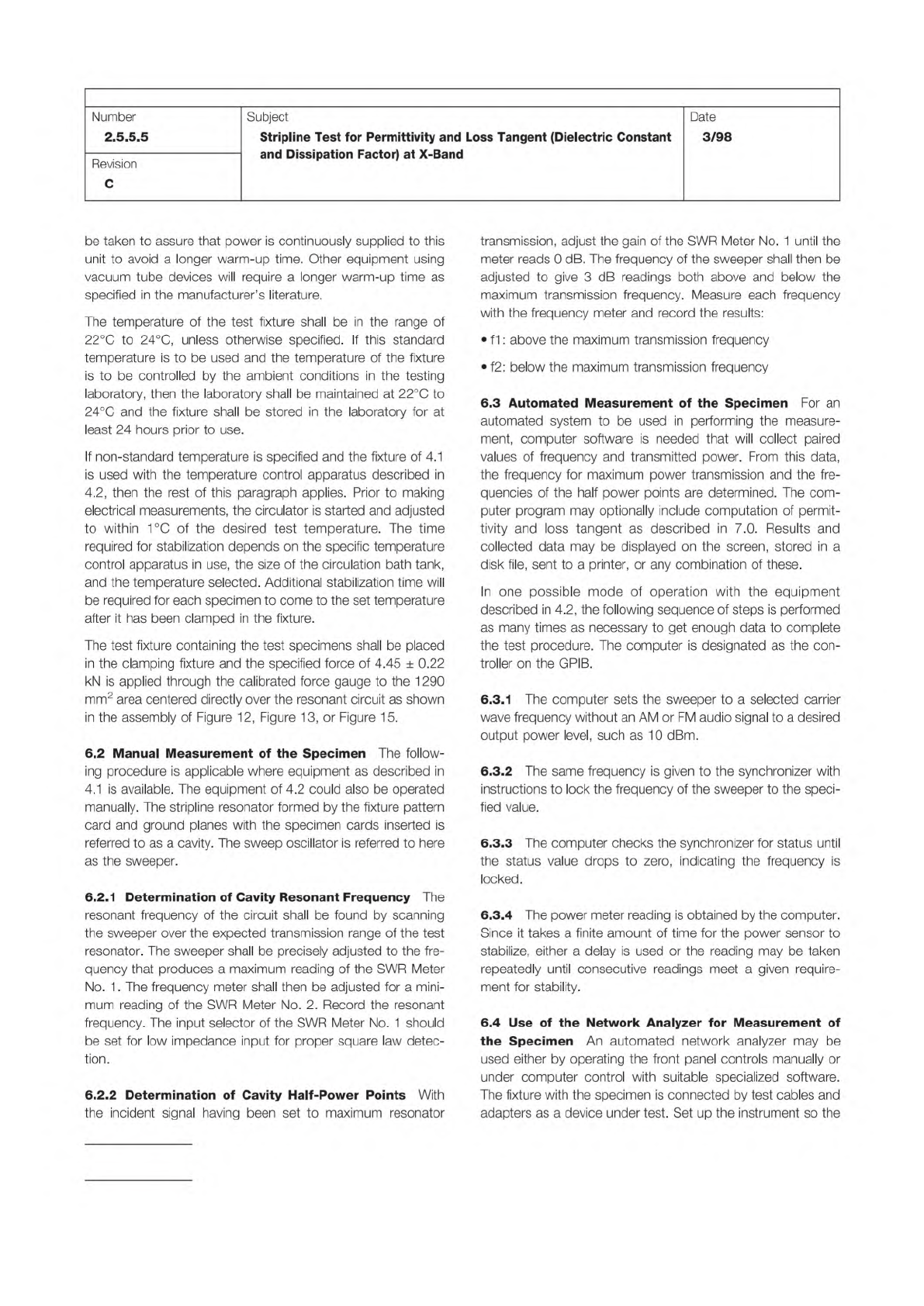
4.2 EBW, RIE, and SET2DIL Apparatus
EBW, RIE, and
SET2DIL utilize a TDR measurement system which
be
composed of a step generator, high-speed sampling oscillo-
scope, and all the necessary accessories for connecting the
TDR unit to the test specimen depicted in Figure 4-3. IPC-
2141 provides a short discussion of the TDR system architec-
ture, system considerations, and the TDR measurement
process.
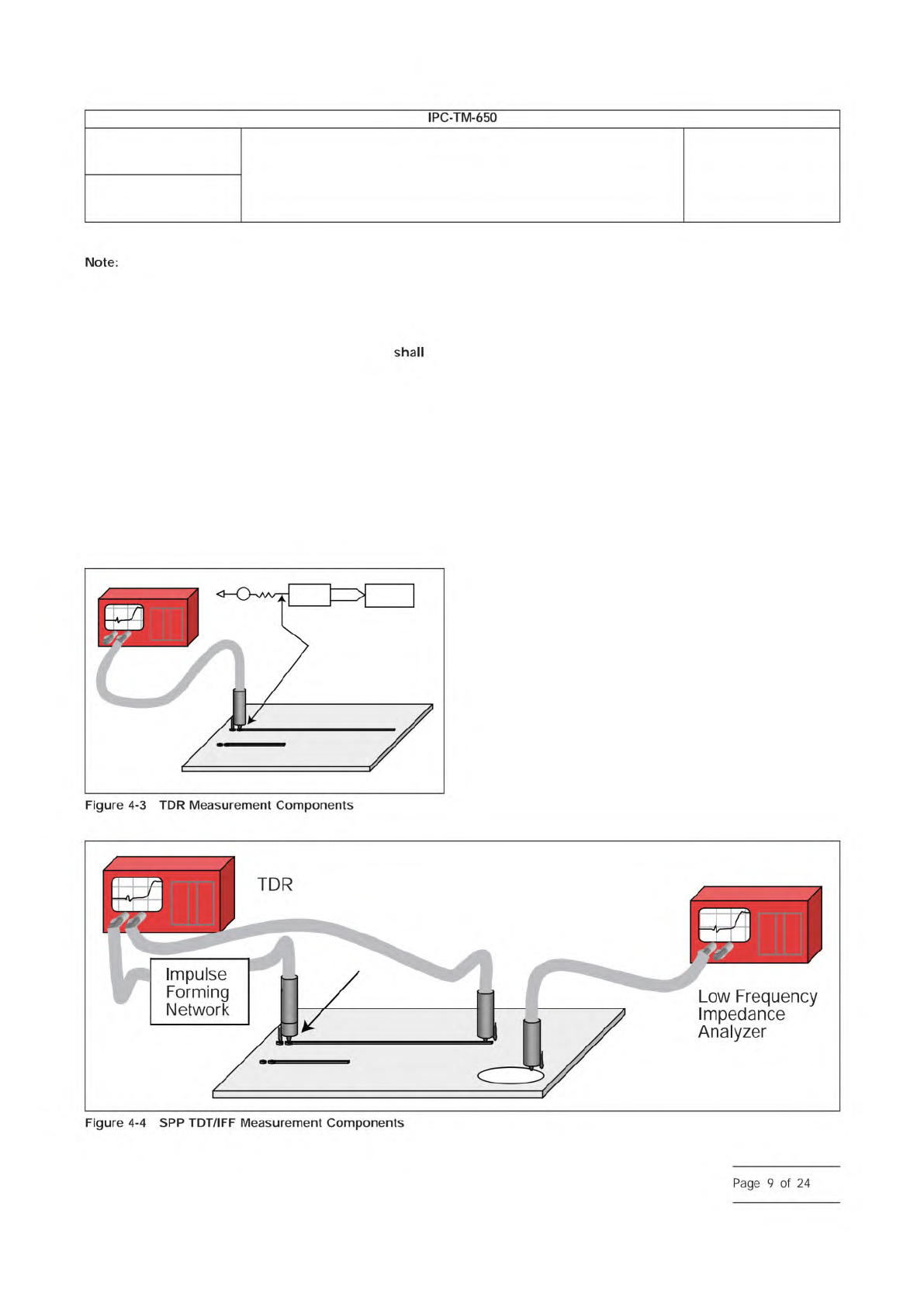
4.3 SPP Apparatus
SPP utilizes a TDR measurement sys-
tem with the addition of one more sampling output head and
impulse forming networks placed between the TDR Sample
head and on probe. This type of setup comprises a TDT sys-
tem as shown in Figure 4-4.
Three general probing solutions may be used. These include:
microprobes, SMA connectors, and handheld probes. Each of
these methods embodies a test structure(s) in near proximity
and on the same printed board layer.
4.4 Measurement System Requirements
4.4.1 System Calibration
Follow the TDR instrument
manufacturer’s recommendation for the frequency of factory
calibration. TDR system ‘‘field’’ checks are to be performed at
regular intervals to ensure proper operation of the test sys-
tembetween the less regular factory calibrations. Field checks
are required for the following reasons:
a) TDR instrument specifications vary with temperature.
b) TDR instrument specifications vary with time (drift).
c) TDR instrument specifications vary due to minor ESD dam-
age.
d) TDR instrument factory calibration may not include auxiliary
components (e.g., cables, probes, etc.).
TDR system field checks should also be performed after a
change of any system component (such as, cable, probes,
etc.). Ensure that the TDR instrument has been operating for
at least 30 minutes prior to any field check or test measure-
ment procedure. Use proper ESD control methods to avoid
damage to the TDR instrument in all field check and test
IPC-25512-4-3
IPC-25512-4-4
Number
2.5.5.12
Subject
Test Methods to Determine the Amount of Signal Loss on
Printed Boards
Date
07/12
Revision
A
IPC-TM-650
Note:
Figure
4-4
SPP
TDT/IFF
Measurement
Components
Page
9
of
24
EBW requirements agreed upon between customer and ven-
dor.
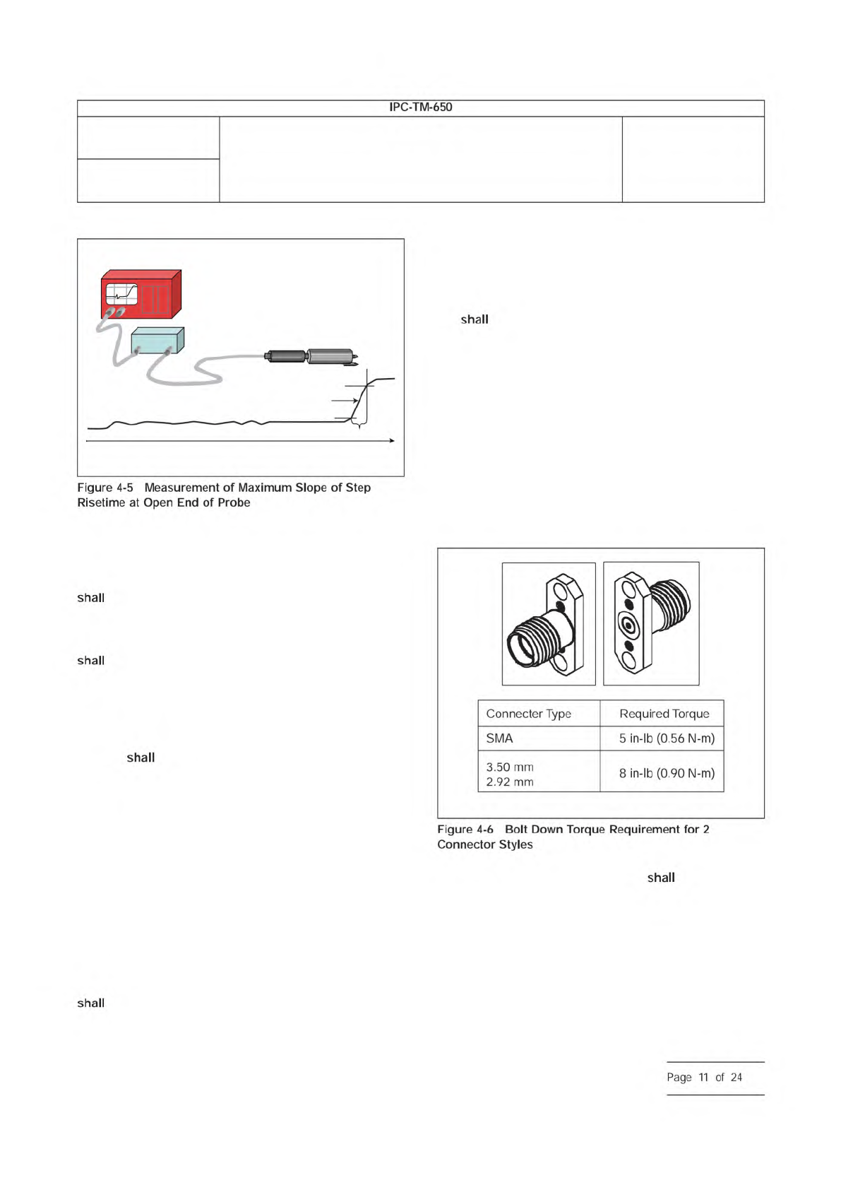
4.4.5.2 RIE Risetime
The rise time (10%-90%) for RIE
be 250 ps or as agreed upon between vendor and cus-
tomer with an open tip of the probe as illustrated in Figure 4-5.
4.4.5.3 SPP Risetime
The rise time (10%-90%) for SPP
be 11 to 35 ps or less at the open tip of the probe or
cable connector as illustrated in Figure 4-5. SPP has an addi-
tional requirement of an impulse forming network to be
located between the TDR head and the test probe.
4.4.5.4 SET2DIL Risetime
The rise time (10-90%) for
SET2DIL
be <35 ps at the open tip of the probe or cable
connector as illustrated in Figure 4-5.
4.4.6 TDR Impedance
The impedance of the TDR unit
should be 50 Ω with an impedance uncertainty less than or
equal to ± 0.5 Ω.
4.4.7 TDR System Calibration
Follow the TDR instrument
manufacturer’s recommendation for the frequency of factory
calibration. Since RIE is related to the ratio of loss, field cali-
bration reverts to insuring proper results from calibration stan-
dards.
4.4.8 SPP Impulse Forming Network Requirement
The
pulse width at the output of the IFN observed at the probe tip
be a minimum of 20 ps. The recommendation is to have
a 20 ps to 60 ps pulse width detected in TDT through the
measurement set-up on typical line lengths used in the test
coupon.
4.4.9 Printed Board Connectors
The TDR cable connec-
tion
utilize a ‘‘SMA,’’ 3.50 mm, or 2.92 mm connectors
at their measurement ports. It is recommended that cable
connections be tightened with a torque wrench to follow
specifications, unless otherwise specified by the manufacturer
of the connector or cable.
Three general probing solutions may be utilized to perform the
SPP extraction: microprobe pads, SMA connectors, and
handheld probes. Surface-mounted SMAs, as shown in Fig-
ure 4-6, are recommended for SPP. They may be either
bolted or slip-fitted into the alignment holes as explained ear-
lier. The bolt-down specification for a Molex SMA style con-
nector, part number 73251-1850, is shown in Figure 4-6.
4.4.10 TDR Cabling
All test cables meet the follow-
ing minimum specifications:
a) Coaxial with a 50 ±1 Ω characteristic impedance
b) 2.92 mm, 3.50 mm, or SMA connectors
c) Max cable insertion loss ≤2.50 dB at 65 GHz, 50 GHz,
40 GHz, or 26.5 GHz, respectively
d) Probing insertion loss ≤0.33 dB at 65 GHz, 50 GHz,
40 GHz, or 26.5 GHz, respectively
IPC-25512-4-5
TDR Instrument
probe
SIU
Maximum
risetime
Rise time
Time
IPC-25512-4-6
Number
2.5.5.12
Subject
Test Methods to Determine the Amount of Signal Loss on
Printed Boards
Date
07/12
Revision
A
IPC-TM-650
—
Figure
4-5
Measurement
of
Maximum
Slope
of
Step
Risetime
at
Open
End
of
Probe
shall
shall
shall
shall
Connecter
Type
Required
Torque
SMA
5
in-lb
(0.56
N-m)
3.50
mm
2.92
mm
8
in-lb
(0.90
N-m)
Figure
4-6
Bolt
Down
Torque
Requirement
for
2
Connector
Styles
shall
Page
11
of
24