IPC-TM-650 EN 2022 试验方法--.pdf - 第443页
Figure 1 X-Band Permittivity T est S etup IPC-TM-650 Page 1 1 of 25 Number 2.5.5.5 Subject Stripline Test for Permittivity and Loss Tangent (Dielectric Constant and Dissipation Factor) at X-Band Date 3/98 Revision C SWEE…
operation is specified in Equation 5-2.
I_R
j
=
RB
j
− RB
j−1
t
j
− t
j−1
I_T
j
=
TB
j
− TB
j−1
t
j
− t
j−1
[5-2]
5.2.2.4 RIE Results
The reference structure, RIE
reference
, is
the square root of the square of the integral of the square of
the impulse response I_R, and can be calculated from J
samples as show in Equation 5-3. The test structure, RIE
test
,
is the square root of the square of the integral of the square
of the impulse response I_T, and is calculated from J samples
as show in Equations 5-3 and 5-4.
RIE
reference
=
√
Σ
j=1
J
I_R
j
2
(t
1
− t
0
)
[5-3]
RIE
test
=
√
Σ
j=1
J
I_T
j
2
(t
1
− t
0
)
[5-4]
The RIE loss in dB, RIE
loss_dB
, is calculated by dB ratio of the
RIE
test
to RIE
reference
as show in Equation 5-5.
RIE
loss_db
= 20 * log
(
RIE
test
RIE
reference
)
[5-5]
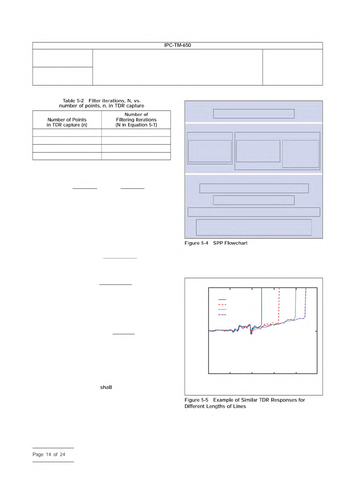
5.3 SPP Procedure
Figure 5-4 summarizes the SPP mea-
surement extraction process.
5.3.1 Selecting Optimum SPP Transmission Lines
SPP
utilizes measurements on two lines of different lengths such as
2.0 cm and 8.0 cm. The pair
be designed to be identi-
cal in every way except for length. The SPP is used to extract
parameters such as α(f) β(f), Γ(f) and Z
0
(f) by utilizing the dif-
ference between the two specimen line lengths. Effects due to
the connectors, cables, probes, and oscilloscope circuitry can
be minimized using this method. Screening the two lines
improves accuracy. Figure 5-5 illustrates lines of similar
design. Accuracy is improved when the slope and deviation
along the lengths of overlaid portions of the respective TDR
waveforms are coincident.
5.3.1.1 Additional SPP Step for Differential Lines
There
are a few additional steps needed when analyzing differential
lines. The TDR screening still needs to be performed first. In
0 > n ≥750 1
750 > n ≥1500 2
1500 > n ≥3000 6
> n >3000 21
TDR
Select best candidates for line pairs
Low Freq
TDT
disc
Determine
1MHzε
r
and Tan δ
(LCR meter)
Determine
Capacitance/unit
length (LCR meter)
Determine
Resistance/unit
length ρ and
(LCR meter)
Lines
Acquire Impulse response for 2 lines of 2 lengths
Window and filter Impulse response
FFT to get Propagation Constant Γ (Attenuation and Phase)
Use itrative matching of Γ, Att, and low freq
parameters to determine tline modeling parameters
IPC-25512-5-5
0.3
0.2
0.25
1.5 2.5
Time (nsec)
Voltage (V)
3.52
1=2 cm
1=5 cm
1=8 cm
1=9.8 cm
3 4
Number
2.5.5.12
Subject
Test Methods to Determine the Amount of Signal Loss on
Printed Boards
Date
07/12
Revision
A
IPC-TM-650
—
Table
5-2
Filter
iterations,
N,
vs.
number
of
points,
n,
in
TDR
capture
Number
of
Points
in
TDR
capture
(n)
Number
of
Filtering
Iterations
(N
in
Equation
5-1)
Figure
5-4
SPP
Flowchart
shall
Figure
5-5
Example
of
Similar
TDR
Responses
for
Different
Lengths
of
Lines
Page
14
of
24
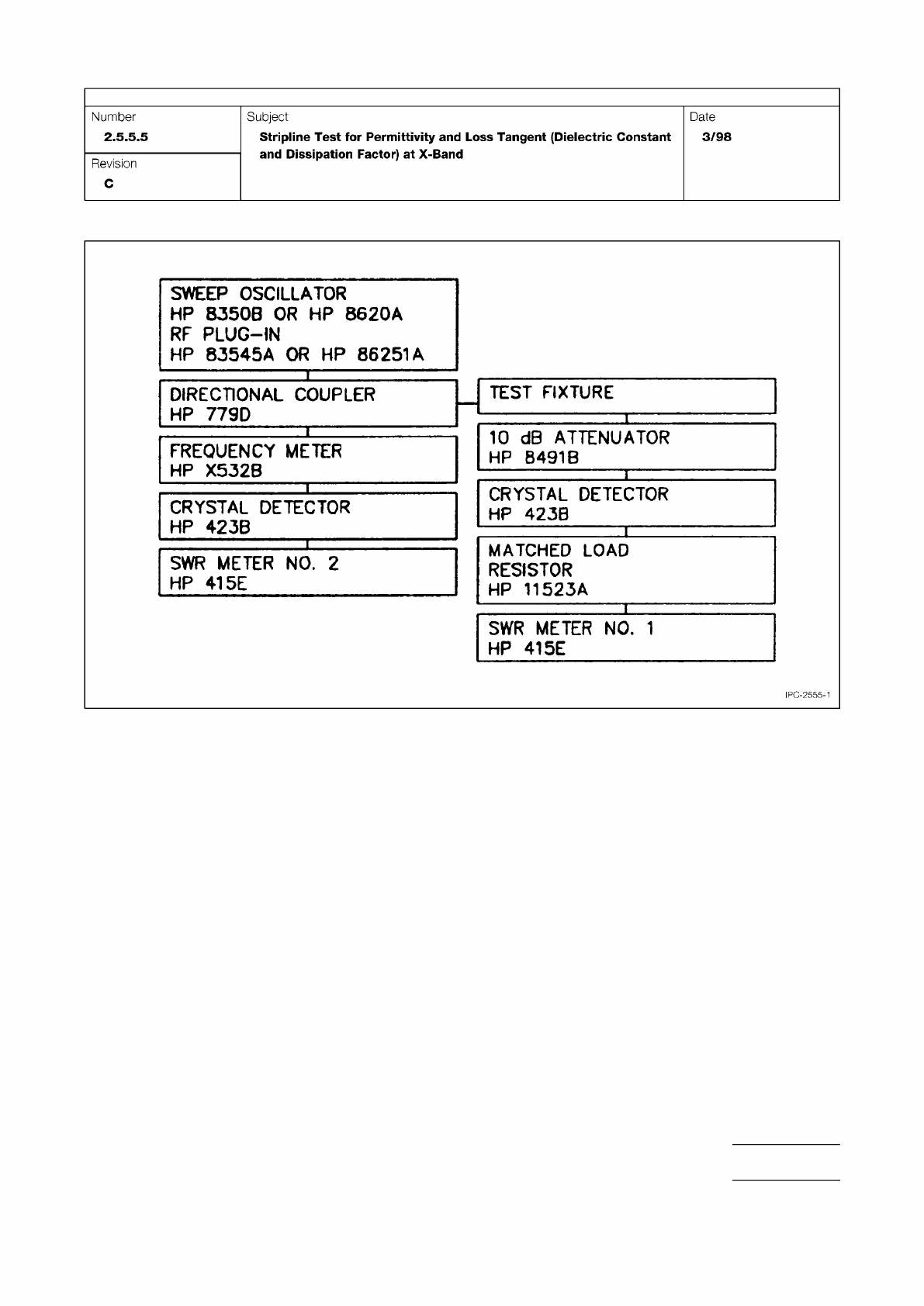
Figure 1 X-Band Permittivity Test Setup
IPC-TM-650
Page 11 of 25
Number
2.5.5.5
Subject
Stripline
Test
for
Permittivity
and
Loss
Tangent
(Dielectric
Constant
and
Dissipation
Factor)
at
X-Band
Date
3/98
Revision
C
SWEEP
OSCILLATOR
HP
8350B
OR
HP
8620A
RF
PLUG-IN
HP
83545A
OR
HP
86251
A
DIRECTIONAL
COUPLER
HP
779D
—
TEST
FIXTURE
I
1
10
dB
ATTENUATOR
HP
8491
B
FREQUENCY
METER
HP
X532B
1
1
CRYSTAL
DETECTOR
HP
423B
CRYSTAL
DETECTOR
HP
423B
1
MATCHED
LOAD
RESISTOR
HP
11523A
SWR
METER
NO.
2
HP
41
5E
1
SWR
METER
NO.
1
HP
41
5E
IPC-2555-1
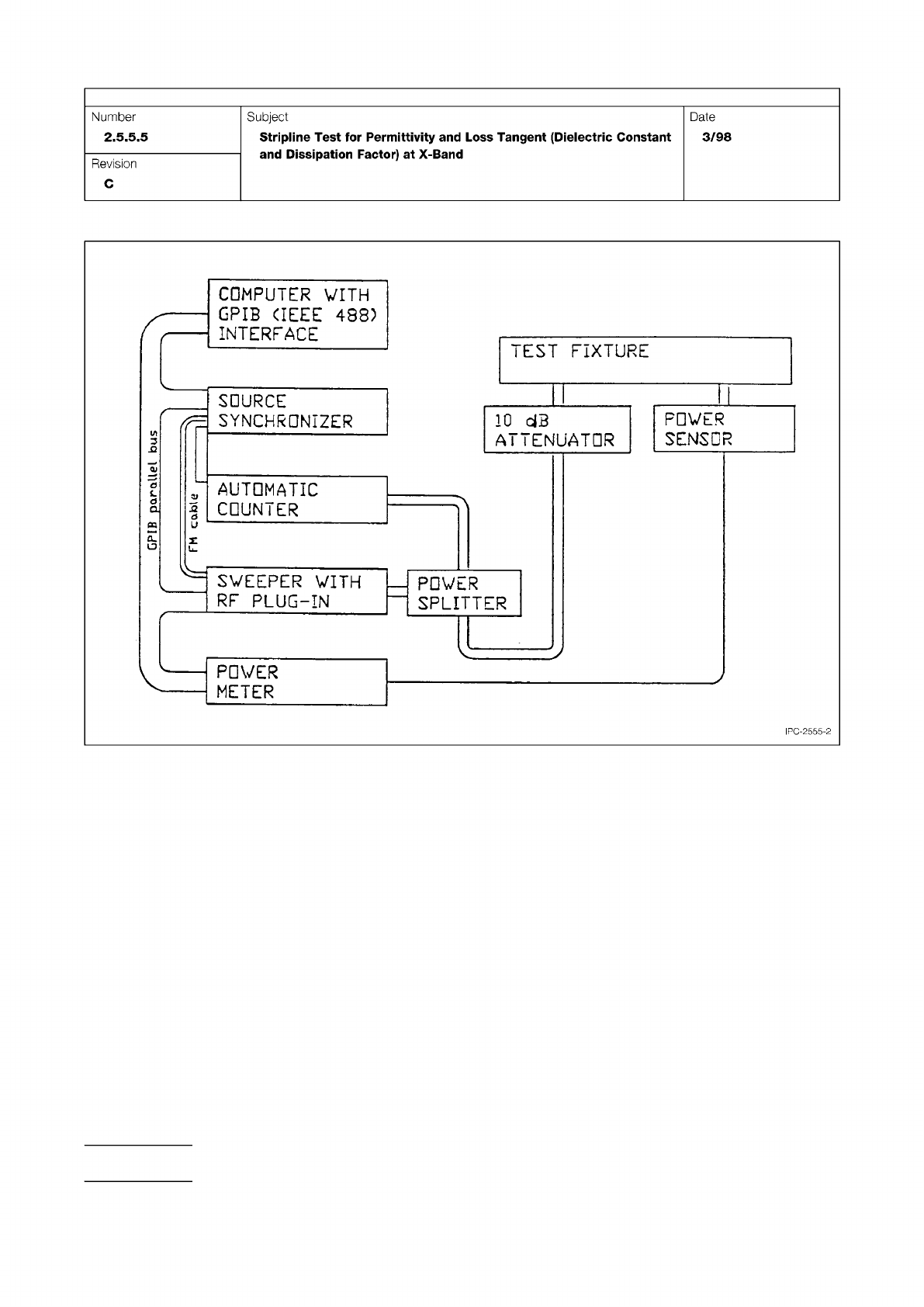
Figure 2 Automated Permittivity Test Setup
IPC-TM-650
Page 12 of 25
AUTOMATIC
COUNTER
SWEEPER
WITH
RF
PLUG-IN
SOURCE
SYNCHRONIZER
II
POWER
SPLITTER
IPC-2555-2
10
dB
ATTENUATOR
PDVER
SENSOR
POWER
METER
COMPUTER
WITH
GPIB
〈IEEE
488)
INTERFACE
TEST
FIXTURE
Number
2.5.5.5
Subject
Stripline
Test
for
Permittivity
and
Loss
Tangent
(Dielectric
Constant
and
Dissipation
Factor)
at
X-Band
Date
3/98
Revision
C
snq
fod