IPC-TM-650 EN 2022 试验方法--.pdf - 第447页
V1(f) and V2(t) is a respective ordered frequency pair A 1 (f) , φ 1 (f) and A 2 (f) , φ 2 (f) . The atte nuation, Att(f) , and phase constant, β (f) , ar e com- puted w ith Equ ations 5- 10 an d 5-11. Γ( , ) = α( , ) + …
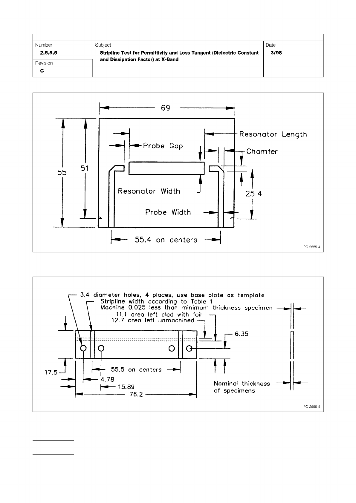
Figure 4 Generalized Resonator Pattern Card Showing Dimensions of Table 1 and Made of Laminate Matching the
Nominal Permittivity of Material to be Tested
Figure 5 Base Stripline Board with Copper Foil and Dielectric Matching the Nominal Permittivity of the Material to be
Tested
IPC-TM-650
Page 14 of 25
Number
2.5.5.5
Subject
Stripline
Test
for
Permittivity
and
Loss
Tangent
(Dielectric
Constant
and
Dissipation
Factor)
at
X-Band
Date
3/98
Revision
C
_L
6.35
Nominal
thickness
of
specimens
55.5
on
centers
4.78
H*—
15.89
76.2
3.4
diameter
holes,
4
places,
use
base
plate
as
template
Stripline
width
according
to
Table
1
Machine
0.025
less
than
minimum
thickness
specimen
11.1
area
left
clad
with
f
1
2.7
area
left
unmachined
17.5
―
B»-
O
G
IPC-2555-5
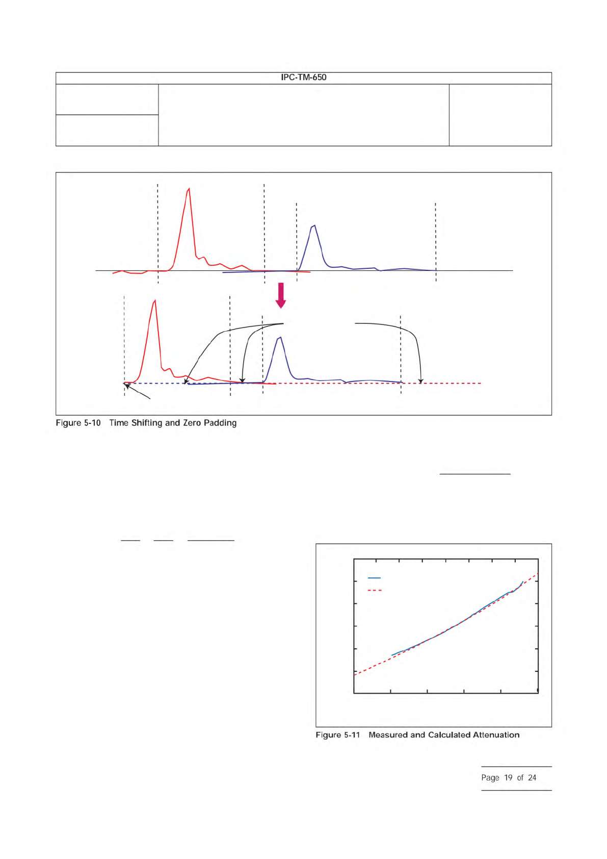
V1(f) and V2(t) is a respective ordered frequency pair A1(f),
φ1(f) and A2(f), φ2(f).
The attenuation, Att(f), and phase constant, β(f), are com-
puted with Equations 5-10 and 5-11.
Γ(,) = α(,) + jβ(,) =
−
1
l
1
– l
2
1n
(
A
1
(,)
A
2
(,)
)
+ j
φ
1
(,) − φ
2
(,)
l
1
− l
2
[5-10]
Att(,) = 20 log (e
Re(Γ(,)
)
β(,) = Im (Γ(F))
[5-11]
5.3.6.3 SPP Broadband Complex Permittivity Extraction
5.3.6.3.1 Frequency Dependent Line Parameters
A 2D
field solver is used to calculate R(f), L(f), C(f), and G(f) per unit
length based on the actual cross sectional dimensions, the
metal resistivity ρ, and low frequency ε
r
and tanδ outlined
above. A 2D solver that assures a causally related calculation
of L-R and C-G is recommended. The initial calculation can
contain a few initial points for ε
r
and tanδ that are used as
starting values for the high-frequency range, for example
3 GHz to 20 GHz. Based on the calculated R(f), L(f), C(f), and
G(f), the attenuation and phase constant are calculated from
Equation 5-12.
Γ(,) = α(,) + jβ(,) =
√
(R + jωL)(G + jωC)
[5-12]
The measured and calculated attenuation and phase are
compared to the measured values as shown in Figure 5-11
and Figure 5-12.
IPC-25512-5-10
0V, 0S
Zero Padded
IPC-25512-5-11
Attenuation (dB/cm)
0.05
0.1
0.2
0.5
1
2
5
1 2 5 10 20 50
Frequency (GHz)
Measured
Calculated
Number
2.5.5.12
Subject
Test Methods to Determine the Amount of Signal Loss on
Printed Boards
Date
07/12
Revision
A
IPC-TM-650
—
Figure
5-10
Time
Shifting
and
Zero
Padding
Figure
5-11
Measured
and
Calculated
Attenuation
Page
19
of
24
Figure
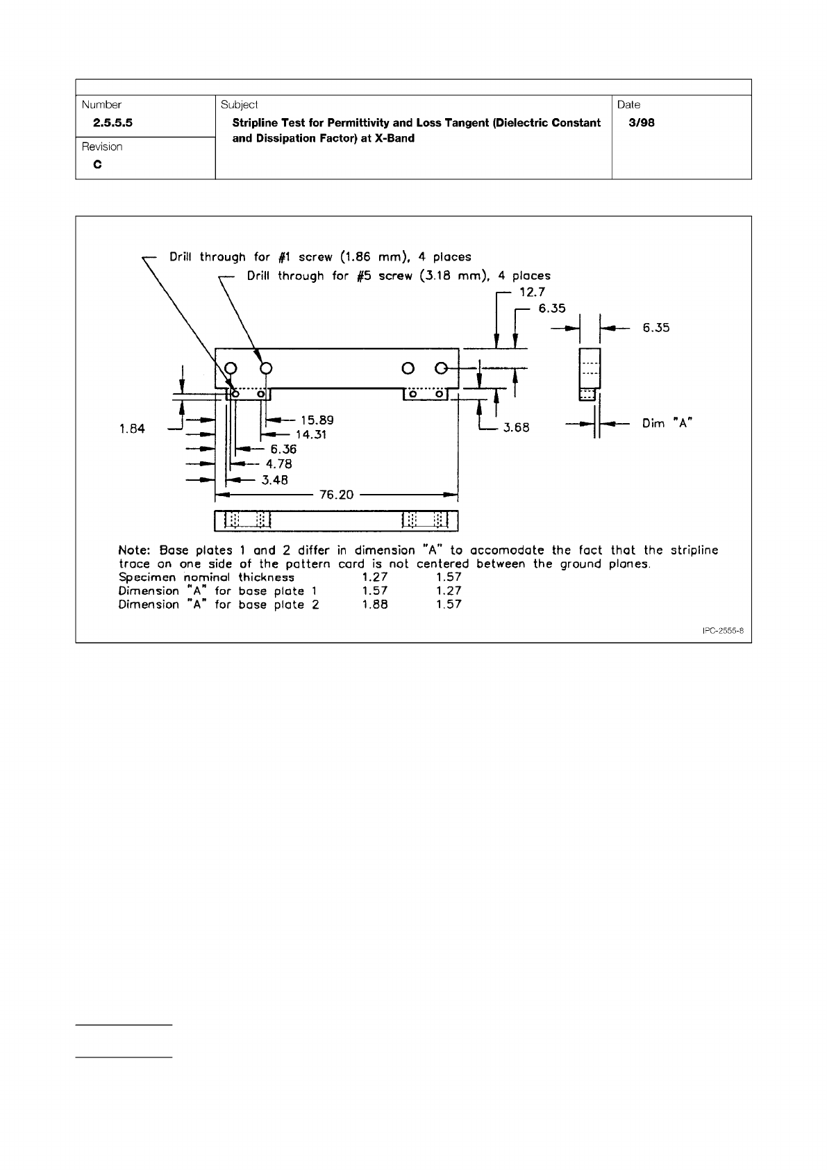
8 Brass or Aluminum Base Plate for Clamping the Base Cards and Connecting Launcher Bodies to the Base Card
IPC-TM-650
Page 16 of 25
Number
2.5.5.5
Subject
Stripline
Test
for
Permittivity
and
Loss
Tangent
(Dielectric
Constant
and
Dissipation
Factor)
at
X-Band
Date
3/98
Revision
C
6.35
o
L£
Dim
"A
76.20
Drill
through
for
#1
screw
(1.86
mm),
4
places
Drill
through
for
#5
screw
(3.18
mm),
4
places
12.7
15.89
14.31
-
•-
6.36
4.78
—
3.48
stripline
Note:
Base
plates
1
and
2
differ
in
dimension
"A”
to
accomodate
the
fact
that
the
trace
on
one
side
of
the
pattern
card
is
not
centered
between
the
ground
planes.
Specimen
hominal
thickness
1.27
1.57
Dimension
“A”
for
base
plate
1
1.57
1.27
Dimension
“A"
for
base
plate
2
L88
1.57
IPC-2555-8