IPC-TM-650 EN 2022 试验方法--.pdf - 第453页
Figure 13 Exploded Side View of Assembly IPC-TM-650 Page 21 o f 25 #5-40 screw and nut i — #1-72 cap screw 三 I Base plate 1 IPC-2555-13 Resonator test pattern board Test specimen Ground plane foil Clomp plate ase plate 2…
5.5.4 Calculating Average Insertion Loss Slope m
a
and
Intercept b
a
For ‘‘N’’ points between frequency range f1 to
f2 the average insertion loss slope and intercept are defined
as follows in Equations 5-15 to 5-18.
,
avg
=
1
N
Σ
n
,
n
[5-15]
IL
avg
=
1
N
Σ
n
IL(,
n
)
[5-16]
m
A
=
1
N
Σ
n
(,
n
− ,
avg
) ⋅ (IL(,
n
) − IL
avg
)
Σ
(,
n
− ,
avg
)
2
[5-17]
b
A
= IL
avg
− m
A
⋅ ,
avg
[5-18]
Suggested values of f1 and f2 are 1 GHz and 5 GHz respec-
tively.
The slope m
a
is a measure of the total frequency dependent
attenuation, α, which is described in IPC-2141.
Number
2.5.5.12
Subject
Test Methods to Determine the Amount of Signal Loss on
Printed Boards
Date
07/12
Revision
A
IPC-TM-650
Page
24
of
24
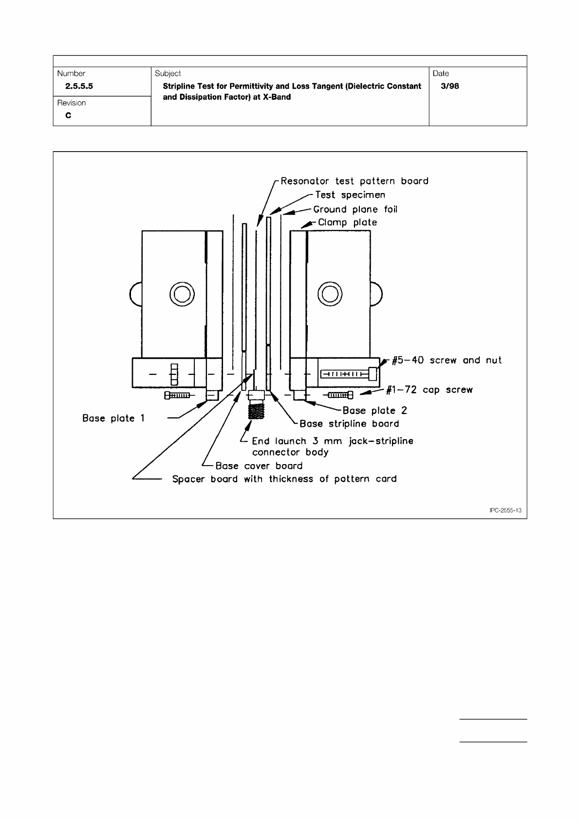
Figure 13 Exploded Side View of Assembly
IPC-TM-650
Page 21 of 25
#5-40
screw
and
nut
i
—
#1-72
cap
screw
三
I
Base
plate
1
IPC-2555-13
Resonator
test
pattern
board
Test
specimen
Ground
plane
foil
Clomp
plate
ase
plate
2
Base
stripline
board
End
launch
3
mm
jack-stripline
connector
body
Base
cover
board
Spacer
board
with
thickness
of
pattern
card
Number
2.5.5.5
Subject
Stripline
Test
for
Permittivity
and
Loss
Tangent
(Dielectric
Constant
and
Dissipation
Factor)
at
X-Band
Date
3/98
Revision
C
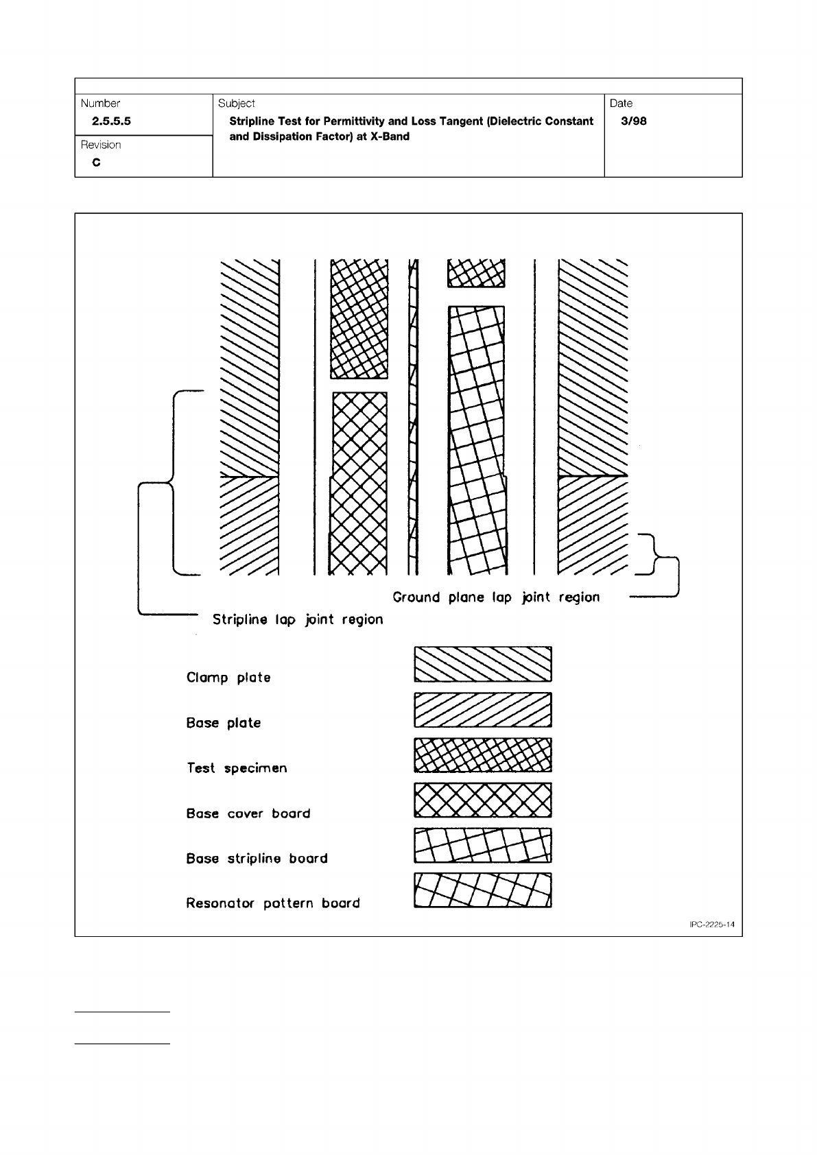
Figure 14 Enlarged Exploded Side View Sectioned Through a Probe Line Showing a Lap Conductor Joint
IPC-TM-650
Page 22 of 25
Number
2.5.5.5
Subject
Stripline
Test
for
Permittivity
and
Loss
Tangent
(Dielectric
Constant
and
Dissipation
Factor)
at
X-Band
Date
3/98
Revision
C
Stripline
lap
joint
region
Clamp
plate
Base
plate
Test
specimen
Base
cover
board
Base
stripline
board
Resonator
pattern
board
IPG-2225-14