IPC-TM-650 EN 2022 试验方法--.pdf - 第456页
4 Measurement Apparatus 4. 1 Sp l it -C yl in de r Re so na to r T he m e th od e m pl oy s a split-cylinder resonator, which i s a cylindrical cavity separated into two halves of equal length, with a dielectric substrat…
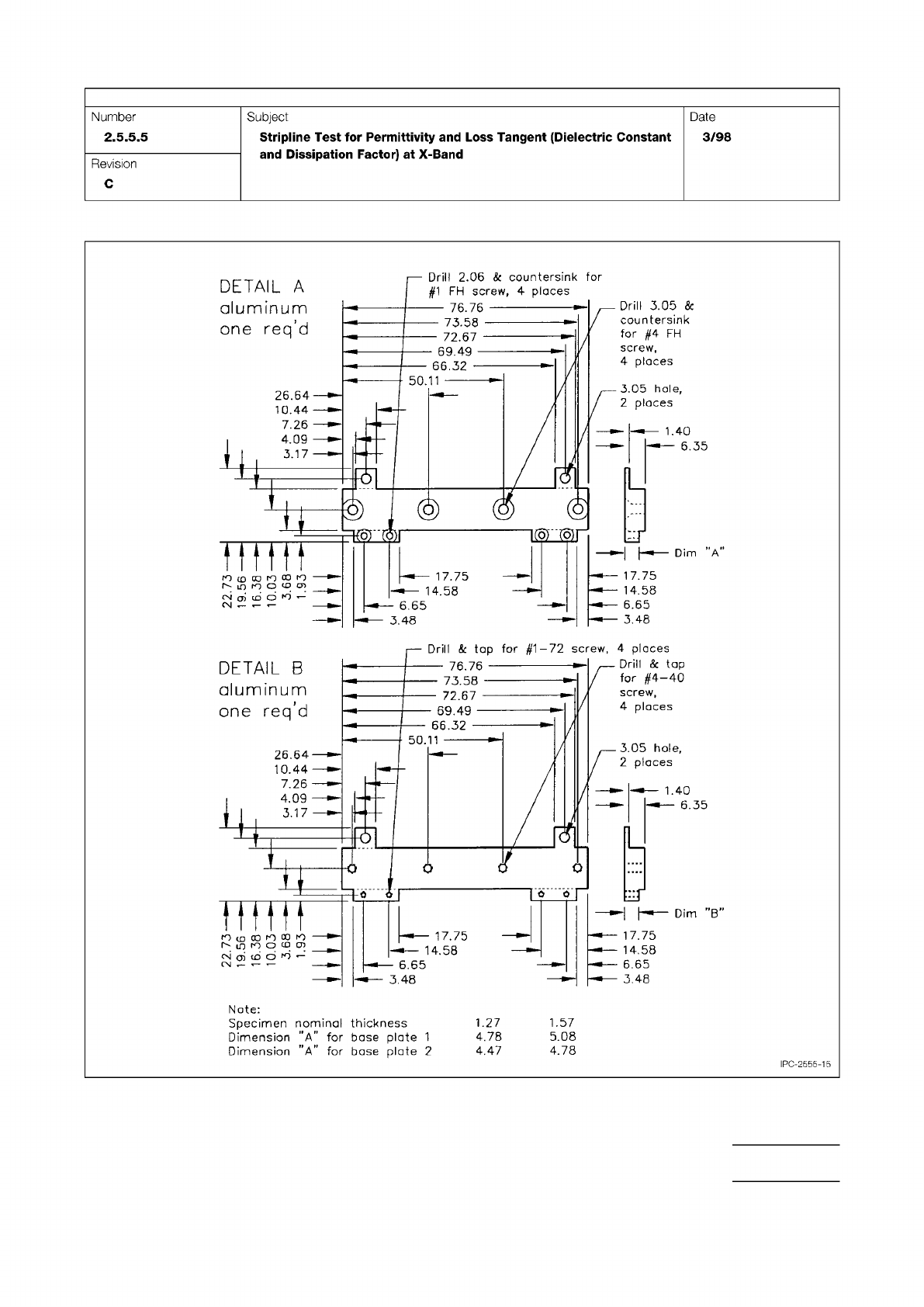
Figure 15 Test Fixture Construction, Older Design
IPC-TM-650
Page 23 of 25
r
50.11
Q
]
0
0
r
Dim
”B”
—
76.76
-
73.58
-
72.67
69.49
-
66.32
-
17.75
14.58
6.65
3.48
3.05
hole,
2
places
Drill
&
tap
for
#4-40
screw,
4
places
Drill
&
tap
for
#1-72
screw,
4
places
17.75
v—
14.58
!■*—
6.65
-
•-
548
—
—
1.40
v
—
6.35
DETAIL
B
aluminum
one
req'd
26.64—
10.44
—
7.26
——
—
4.09
—
3.17
—
Nate:
Specimen
nominal
thickness
1.27
1.57
Dimension
"A"
for
base
plate
1
4.78
5.08
Dimension
"A"
for
base
plate
2
4.47
4.78
©
©
©
K3F
mrn
A
17.75
14.58
17.75
14.58
6.65
3.48
3.05
hole,
2
places
DETAIL
A
aluminum
one
req'd
Drill
3.05
&
countersink
for
#4
FH
screw,
4
places
Drill
2.06
&
countersink
for
#1
FH
screw,
4
places
—
76.76
一
73.58
-
72.67
-
69.49
-
66.32
—
50.11
26.64
10.44
7.26
——
4.09
—
3.17
6.65
3.48
二
及
l)
=K5F
册
1.40
6.35
PC-2555-15
Number
2.5.5.5
Subject
Stripline
Test
for
Permittivity
and
Loss
Tangent
(Dielectric
Constant
and
Dissipation
Factor)
at
X-Band
Date
3/98
Revision
C
r-TTHn
29.0
n
OL
996L
R7Z
4 Measurement Apparatus
4.1 Split-Cylinder Resonator
The method employs a
split-cylinder resonator, which is a cylindrical cavity separated
into two halves of equal length, with a dielectric substrate
placed in the gap between the two cavity sections. The split-
cylinder resonator must be constructed to allow an adjustable,
variable gap between the two cavity sections for introduction
of the dielectric substrate. Additional details about the con-
struction of a split-post resonator are given in the references
described in 6.2. Over the years there have been commercial
manufacturers of this fixture.
In order to excite and detect the desired fundamental TE
011
resonant mode in the split-cylinder resonator, a coupling loop
is introduced, through a small hole in the cavity wall, in each
of the two cavity regions. The plane of the coupling loop
should be parallel to the plane of the sample, in order to allow
maximum interaction with the vertical component of the mag-
netic field. Each of the coupling loops is connected to a
coaxial transmission line that is connected to the input port of
a network analyzer. To minimize the effect of coupling losses,
the distance to which the loops extend radially into each of the
cavity sections must also be adjustable. In addition to the fun-
damental TE
011
mode, higher modes can be used to extend
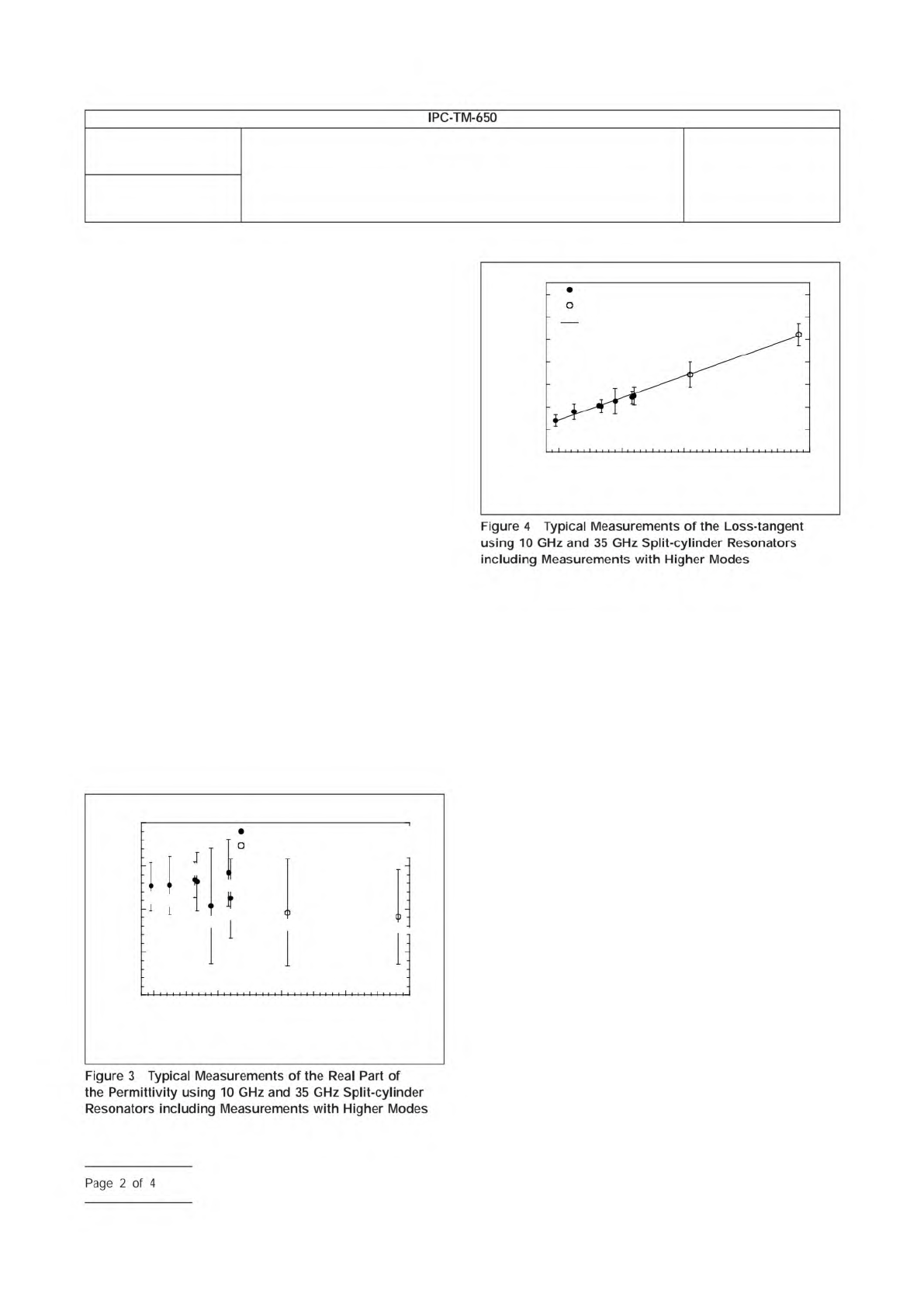
the measurement frequency. Typical measurements on fused
silica with higher mode measurements are shown in Figures 3
and 4.
4.2 Network Analyzer
A scalar or vector network analyzer
is necessary to perform the measurement with the split-
cylinder resonator. Commercially available network analyzers
operate over various frequency ranges, so care is needed to
ensure that the network analyzer covers the necessary fre-
quency range for the particular split-cylinder resonator used.
4.3 Digital Micrometer
The dielectric substrate thickness
can be measured with a digital micrometer with a minimal
resolution of 0.001 mm [0.000039 in].
5 Procedure
5.1
Turn on the network analyzer and allow the unit to
warm-up and stabilize according to the manufacturer’s
instructions.
5.2
Connect the network analyzer’s two input ports to the
split-cylinder resonator’s coupling loops using coaxial trans-
mission lines.
5.3
Measure the thickness of the substrate over several
locations using a digital micrometer, and compute the mean
substrate thickness.
5.4
Determine split-cylinder resonator properties. The
length, radius and conductivity of the split-cylinder resonator
must be known before the substrate relative permittivity and
loss tangent can be calculated. If these variables have not
been already determined, the following procedure can be
used:
IPC-25513-3
3.90
10 20
Frequency (GHz)
30 40 50
3.85
3.80
3.75
3.70
Relative Permittivity
10 GHz Split-Cylinder Resonator
35 GHz Split-Cylinder Resonator
TE
011
TE
013
TE
021
TE
023
TE
017
TE
025
TE
011
TE
013
TE
015
IPC-25513-4
7x10
-4
6
5
4
3
2
1
0
10 20
Frequency (GHz)
30 40 50
Loss Tangent
35 GHz Split-Cylinder Resonator
Linear Least Squares Fit
10 GHz Split-Cylinder Resonator
TE
011
TE
013
TE
021
TE
023
TE
017
TE
025
TE
011
TE
013
TE
015
Number
2.5.5.13
Subject
Relative Permittivity and Loss Tangent Using a Split-Cylinder
Resonator
Date
01/07
Revision
IPC-TM-650
Figure
4
Typical
Measurements
of
the
Loss-tangent
using
10
GHz
and
35
GHz
Split-cylinder
Resonators
including
Measurements
with
Higher
Modes
Figure
3
Typical
Measurements
of
the
Real
Part
of
the
Permittivity
using
10
GHz
and
35
GHz
Split-cylinder
Resonators
including
Measurements
with
Higher
Modes
Page
2
of
4
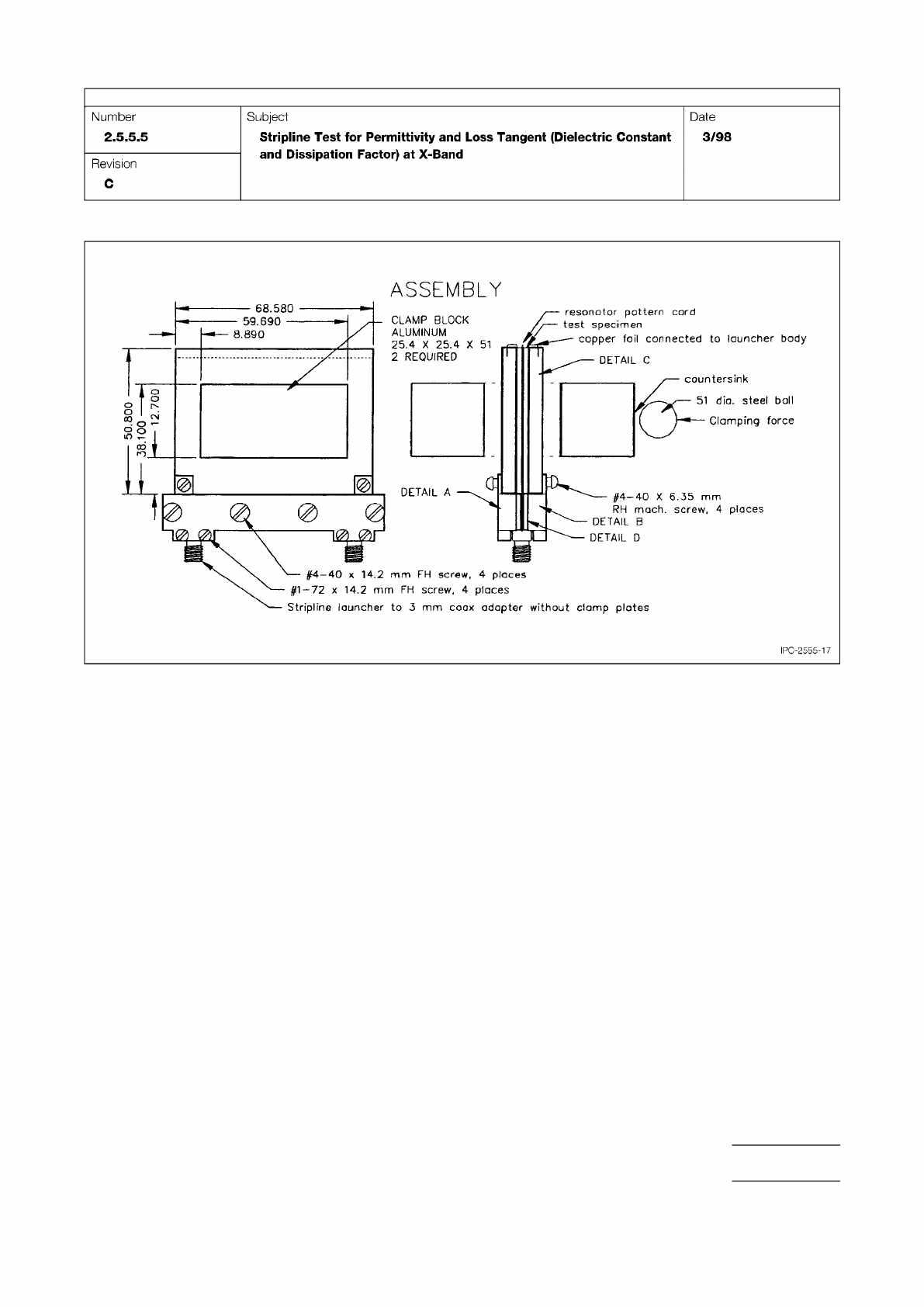
Figure 17 Test Fixture Construction, Older Design (Continued)
IPC-TM-650
Page 25 of 25
ASSEMBLY
51
DETAIL
C
countersink
51
dio.
steel
ball
Clamping
force
DETAIL
A
#4一40
X
6.35
mm
s
4
places
IPC-2555-17
•
•
'
CLAMP
BLOCK
ALUMINUM
25.4
X
25.4
X
2
REQUIRED
—
68.580
-
59.690
-
8.890
RH
mach.
screw,
4
places
DETAIL
B
DETAIL
D
resonator
pattern
cord
test
specimen
copper
foil
connected
to
launcher
body
#1-72
x
14.2
mm
FH
screw,
4
places
Stripline
launcher
to
3
mm
coax
adapter
without
clamp
plotes
#4—40
x
14,2
mm
FH
screw.
Number
2.5.5.5
Subject
Stripline
Test
for
Permittivity
and
Loss
Tangent
(Dielectric
Constant
and
Dissipation
Factor)
at
X-Band
Date
3/98
Revision
C
oo
-
o
1n