IPC-TM-650 EN 2022 试验方法--.pdf - 第475页
Step 1 – IPC-TM-650 Page 7 of 23 Number 2.5.5.7 Subject Characteristic Impedance of Lines on Printed Boards by TDR Date 03/04 Revision A sufficient robustness so that its impedance remains constant between calibration cy…
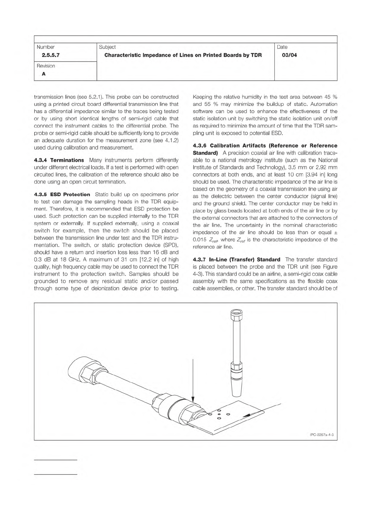
Figure 4-3 Reference Airline and Probe Contact Pad
REFERENCE
AIRLINE
PROBE
TRANSFER
STANDARD
PROBE
CONTACT
PAD
ADAPTOR
IPC-TM-650
Page 6 of 23
Number
2.5.5.7
Subject
Characteristic
Impedance
of
Lines
on
Printed
Boards
by
TDR
Date
03/04
Revision
A
transmission
lines
(see
5.2.1).
This
probe
can
be
constructed
using
a
printed
circuit
board
differential
transmission
line
that
has
a
differential
impedance
similar
to
the
traces
being
tested
or
by
using
short
identical
lengths
of
semi-rigid
cable
that
connect
the
instrument
cables
to
the
differential
probe.
The
probe
or
semi-rigid
cable
should
be
sufficiently
long
to
provide
an
adequate
duration
for
the
measurement
zone
(see
4.1
.2)
used
during
calibration
and
measurement.
4.3.4
Terminations
Many
instruments
perform
differently
under
different
electrical
loads.
If
a
test
is
performed
with
open
circuited
lines,
the
calibration
of
the
reference
should
also
be
done
using
an
open
circuit
termination.
4.3.5
ESD
Protection
Static
build
up
on
specimens
prior
to
test
can
damage
the
sampling
heads
in
the
TDR
equip¬
ment.
Therefore,
it
is
recommended
that
ESD
protection
be
used.
Such
protection
can
be
supplied
internally
to
the
TDR
system
or
externally.
If
supplied
externally,
using
a
coaxial
switch
for
example,
then
the
switch
should
be
placed
between
the
transmission
line
under
test
and
the
TDR
instru¬
mentation.
The
switch,
or
static
protection
device
(SPD),
should
have
a
return
and
insertion
loss
less
than
16
dB
and
0.3
dB
at
18
GH
乙
A
maximum
of
31
cm
[12.2
in]
of
high
quality,
high
frequency
cable
may
be
used
to
connect
the
TDR
instrument
to
the
protection
switch.
Samples
should
be
grounded
to
remove
any
residual
static
and/or
passed
through
some
type
of
deionization
device
prior
to
testing.
Keeping
the
relative
humidity
in
the
test
area
between
45
%
and
55
%
may
minimize
the
buildup
of
static.
Automation
software
can
be
used
to
enhance
the
effectiveness
of
the
static
isolation
unit
by
switching
the
static
isolation
unit
on/off
as
required
to
minimize
the
amount
of
time
that
the
TDR
sam¬
pling
unit
is
exposed
to
potential
ESD.
4.3.6
Calibration
Artifacts
(Reference
or
Reference
Standard)
A
precision
coaxial
air
line
with
calibration
trace¬
able
to
a
national
metrology
institute
(such
as
the
National
Institute
of
Standards
and
Technology),
3.5
mm
or
2.92
mm
connectors
at
both
ends,
and
at
least
10
cm
[3.94
in]
long
should
be
used.
The
characteristic
impedance
of
the
air
line
is
based
on
the
geometry
of
a
coaxial
transmission
line
using
air
as
the
dielectric
between
the
center
conductor
(signal
line)
and
the
ground
shield.
The
center
conductor
may
be
held
in
place
by
glass
beads
located
at
both
ends
of
the
air
line
or
by
the
external
connectors
that
are
attached
to
the
connectors
of
the
air
line.
The
uncertainty
in
the
nominal
characteristic
impedance
of
the
air
line
should
be
less
than
or
equal
±
0.015
乙
白
力
where
Zref
is
the
characteristic
impedance
of
the
reference
air
line.
4.3.7
In-Line
(Transfer)
Standard
The
transfer
standard
is
placed
between
the
probe
and
the
TDR
unit
(see
Figure
4-3).
This
standard
could
be
an
airline,
a
semi-rigid
coax
cable
assembly
with
the
same
specifications
as
the
flexible
coax
cable
assemblies,
or
other.
The
transfer
standard
should
be
of
Step 1 –
IPC-TM-650
Page 7 of 23
Number
2.5.5.7
Subject
Characteristic
Impedance
of
Lines
on
Printed
Boards
by
TDR
Date
03/04
Revision
A
sufficient
robustness
so
that
its
impedance
remains
constant
between
calibration
cycles.
4.3.8
Adapter,
Airline-to-Probe
Contact
Pad
A
preferred
method
of
calibrating
the
TDR
amplitude
response
is
to
con¬
nect
a
probe
contact
pad
directly
to
the
airline
and
to
probe
the
airline
through
the
contact
pad
(see
Figure
4-3).
The
con¬
tact
pad
should
have
a
nominal
characteristic
impedance
of
50
Q
±
1
.0
Q.
An
increase
in
measurement
accuracy
can
be
achieved
by
using
a
reference
impedance
standard
that
is
closely
matched
to
the
impedance
of
the
transmission
line
to
be
tested.
5
Procedures
5.1
Measurement
Preliminaries
In
this
section,
common
considerations
for
the
calibration
of
the
TDR
measurement
system
and
performing
the
TDR
measurements
are
provided.
5.1
.3
describes
a
method
for
establishing
the
measurement
zone
that
can
be
applied
to
the
measurement
methods
described
in
5.2
and
5.3.
5.1.1
System
Calibration
Follow
the
TDR
instrument
manufacturer's
recommendation
for
the
frequency
of
factory
calibration.
TDR
system
"field"
calibrations
are
to
be
per¬
formed
at
regular
intervals
in
addition
to
the
less
regular
fac¬
tory
calibrations.
The
field
calibrations
are
required
for
the
fol¬
lowing
reasons:
a.
TDR
instrument
specifications
vary
with
temperature.
b.
TDR
instrument
specifications
vary
with
time
(drift).
c.
TDR
instrument
specifications
vary
due
to
minor
ESD
dam¬
age.
d.
TDR
instrument
factory
calibration
usually
does
not
include
user
supplied
auxiliary
components
(e.g.,
cables,
probes,
etc.).
TDR
system
field
calibrations
should
also
be
performed
after
a
change
of
any
system
component
(such
as,
cable,
probes,
etc.).
Ensure
that
the
TDR
instrument
has
been
operating
for
at
least
30
minutes
prior
to
any
calibration
or
test
measure¬
ment
procedure.
Use
proper
ESD
control
methods
to
avoid
damage
to
the
TDR
instrument
in
all
calibration
and
test
measurement
proce¬
dures.
ESD
control
components
can
include
static
dissipative
mats,
deionizer
systems,
and
operator
gowning.
5.1.2
Premeasurement
Checks
The
test
measurement
should
be
performed
after
the
completion
of
the
calibration
process.
Ensure
that
plane
of
the
signal
line
of
a
microstrip
(or
embedded
microstrip)
structure
is
at
least
a
distance
equal
to
six
times
the
width
of
the
microstrip
signal
line
from
any
mate¬
rial
(such
as
the
testing
table)
that
can
affect
the
dielectric
environment
of
the
microstrip
line.
If
the
tests
are
being
con¬
ducted
with
hand
probe(s),
care
must
be
taken
to
ensure
that
the
hands
and/or
arms
of
the
operator
do
not
contact
any
surface
of
the
board
over
the
transmission
line
being
tested.
Probes
should
be
applied
to
the
test
points
with
sufficient
force
to
ensure
proper
electrical
contact
between
the
trace
and
the
probe
assembly.
Consistent
application
(that
is,
force,
angle
of
placement,
etc.)
of
the
probes
onto
the
test
points
is
important
to
ensure
repeatable
measurement
results.
Before
recording
any
measurement
results,
ensure
that
the
TDR
waveform
is
stable
(that
is,
not
drifting
in
amplitude
or
time)
otherwise
measurement
error
will
occur.
To
improve
the
accuracy
of
the
impedance
measurement,
it
is
important
to
optimize
the
vertical
gain
setting
(typically
in
V/div
or
p/div)
and
horizontal
axis
setting
(typically
in
time/div)
of
the
TDR
unit
so
as
to
maximize
the
duration
of
the
measurement
zone
within
the
TDR
waveform
and
to
increase
amplitude
resolution.
Per¬
form
this
TDR
adjustment
prior
to
acquiring
any
TDR
wave¬
forms
from
which
Zo
will
be
computed.
Ensure
that
the
tem¬
perature
and
humidity
of
the
test
environment
is
within
TDR
instrument
specifications
and
is
stable.
5.1.3
Establishing
the
Measurement
Zone
The
value
of
the
measurement
zone
is
critical
to
the
accuracy
and
repeat¬
ability
of
the
TDR
measurement
process.
Measurement
zone
differences
are
a
large
factor
in
correlation
problems
between
measurements.
The
measurement
zone
should
be
set
repeat¬
ability
for
each
transmission
line
independent
of
the
type
of
dielectric
material
surrounding
the
transmission
line
or
its
structure
(surface
microstrip,
embedded
microstrip,
stripline,
differential
pair,
etc.).
The
following
process
can
be
incorpo¬
rated
into
the
test
measurement
process.
There
are
two
mea¬
surement
zones,
one
for
the
transmission
line
under
test
(see
5.1
.3.1)
and
one
for
the
reference
(see
5.1
.3.2),
which
may
be
either
a
transfer
standard
or
a
coaxial
air
line.
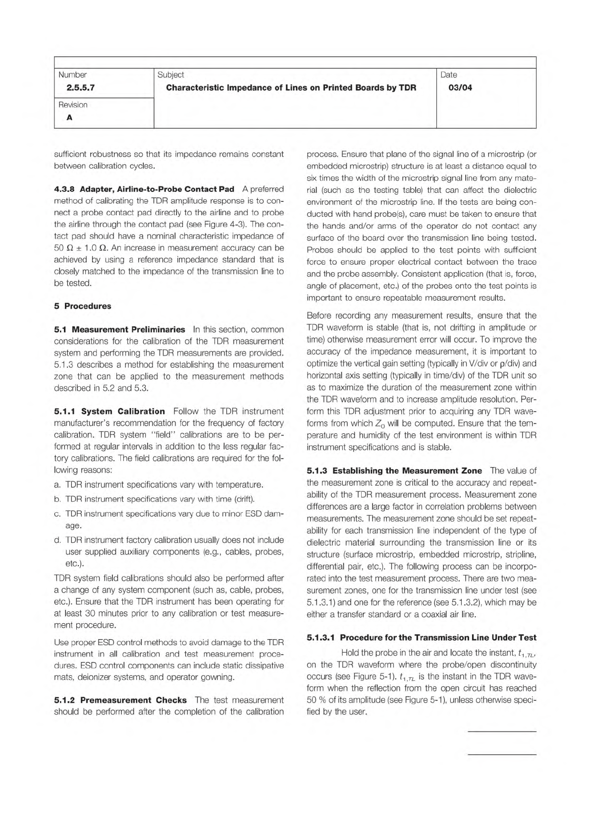
5.1.
3.1
Procedure
for
the
Transmission
Line
Under
Test
Hold
the
probe
in
the
air
and
locate
the
instant,
tA
TL,
on
the
TDR
waveform
where
the
probe/open
discontinuity
occurs
(see
Figure
5-1).
力
兀
is
the
instant
in
the
TDR
wave¬
form
when
the
reflection
from
the
open
circuit
has
reached
50
%
of
its
amplitude
(see
Figure
5-1),
unless
otherwise
speci¬
fied
by
the
user.
Step 2 –
Step 3 –
Step 4 –
Step 5 –
Figure 5-1 Determination of instant in the TDR waveform corresponding to the beginning of the transmission line. A
R,1
is
the amplitude of the signal reflected from the open end of the probe. SPD is the static protection device (see 4.3.5).
PROBE
SPD
TDR
INSTRUMENT
PRECISION
RF CABLE
TRANSFER
STANDARD
TIME
0.5A
R,1
t
1,TL
A
R,1
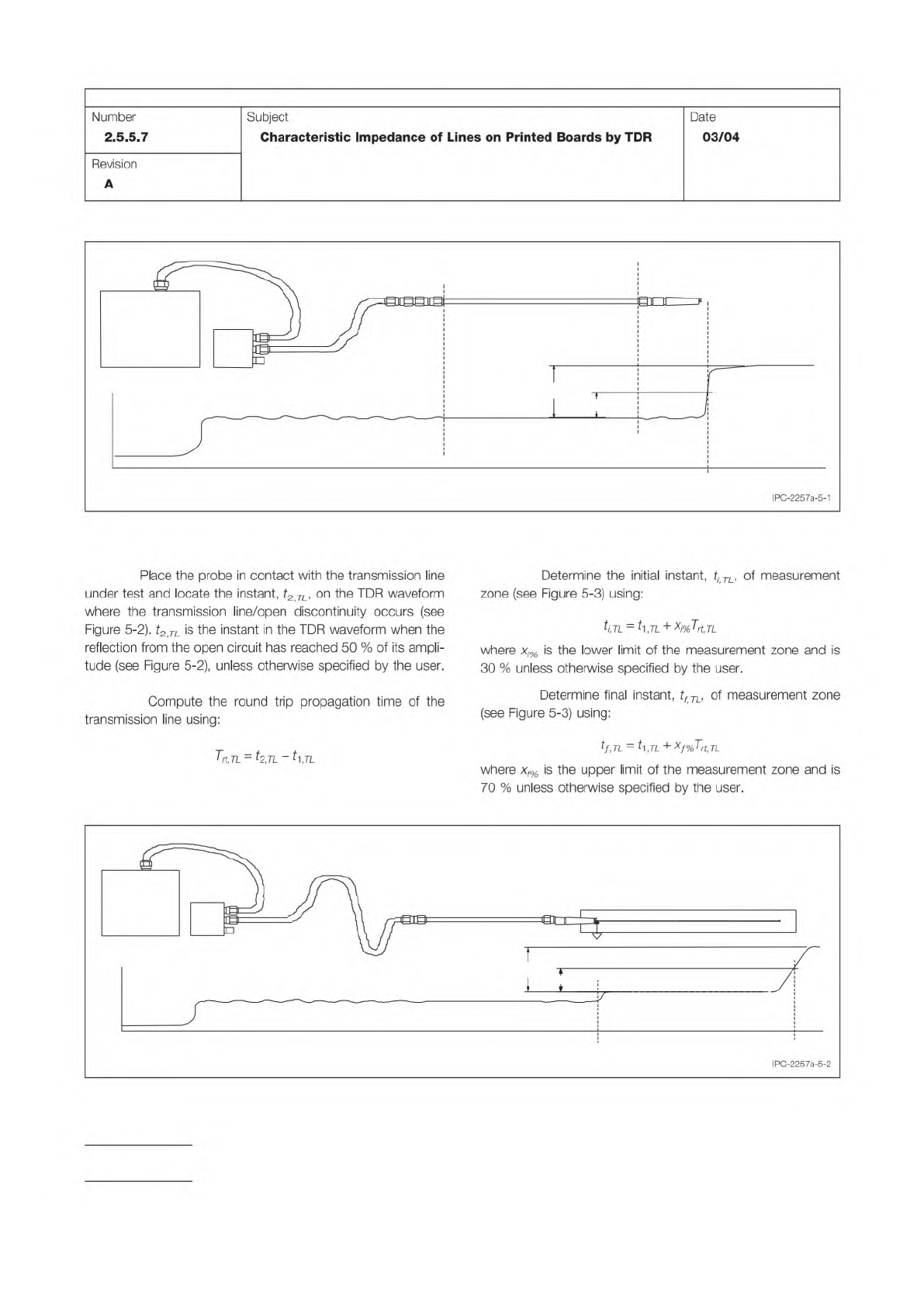
Figure 5-2 Determination of instant in TDR waveform corresponding to the end of the transmission line.
A
R,2
is the
amplitude of the signal reflected from the open end of the transmission line under test.
SPD
TRANSFER
STANDARD
TDR
INSTRUMENT
TRANSMISSION LINE UNDER TEST
0.5
A
R2
TIME
t
1,TL
t
2,TL
A
R2
PRECISION
RF CABLE
IPC-TM-650
Page 8 of 23
Number
2.5.5.7
Subject
Characteristic
Impedance
of
Lines
on
Printed
Boards
by
TDR
Date
03/04
Revision
A
Place
the
probe
in
contact
with
the
transmission
line
under
test
and
locate
the
instant,
t2
TL,
on
the
TDR
waveform
where
the
transmission
line/open
discontinuity
occurs
(see
Figure
5-2).
t2
TL
is
the
instant
in
the
TDR
waveform
when
the
reflection
from
the
open
circuit
has
reached
50
%
of
its
ampli¬
tude
(see
Figure
5-2),
unless
otherwise
specified
by
the
user.
Compute
the
round
trip
propagation
time
of
the
transmission
line
using:
Trt,TL
=
—71
-
力
,71
Determine
the
initial
instant,
tj
TL,
of
measurement
zone
(see
Figure
5-3)
using:
ti,TL
=
力,71
+
Xj%T
也
tl
where
xj%
is
the
lower
limit
of
the
measurement
zone
and
is
30
%
unless
otherwise
specified
by
the
user.
Determine
final
instant,
tf
TU
of
measurement
zone
(see
Figure
5-3)
using:
tf,TL
=
片,几
+xf%Trt,TL
where
xf%
is
the
upper
limit
of
the
measurement
zone
and
is
70
%
unless
otherwise
specified
by
the
user.
IPC-2257a-5-2