IPC-TM-650 EN 2022 试验方法--.pdf - 第477页
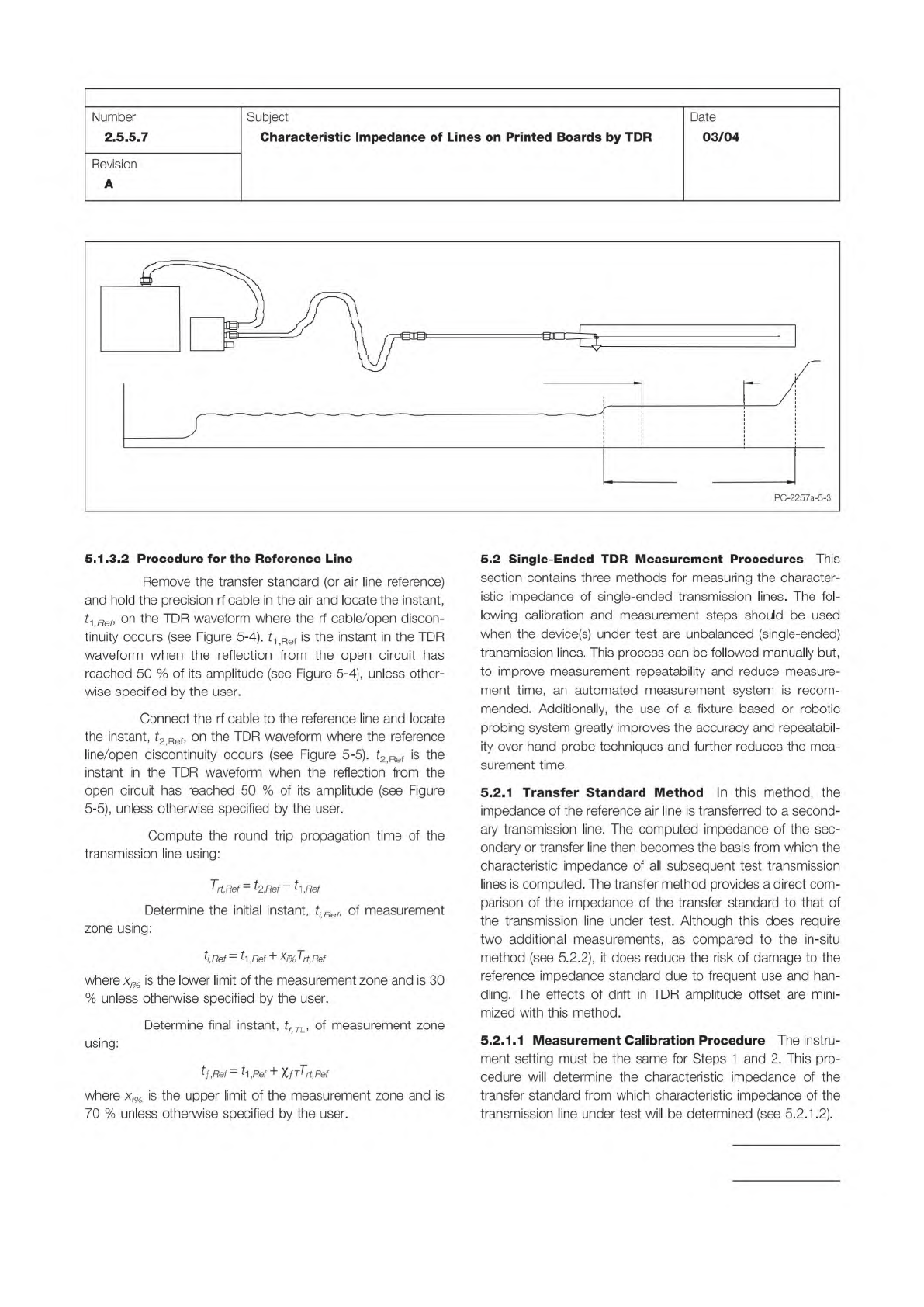
Step 1 – Step 2 – Step 3 – Step 4 – Step 5 – Figure 5-3 Determination of Measurement Zon e T rt ,TL TIME t 1,TL t 2,TL SPD TRANSFER STANDARD TDR INSTRUMENT TRANSMISSION LINE UNDER TEST t i,TL t f,TL MEASUREMENT ZONE for …
Step 2 –
Step 3 –
Step 4 –
Step 5 –
Figure 5-1 Determination of instant in the TDR waveform corresponding to the beginning of the transmission line. A
R,1
is
the amplitude of the signal reflected from the open end of the probe. SPD is the static protection device (see 4.3.5).
PROBE
SPD
TDR
INSTRUMENT
PRECISION
RF CABLE
TRANSFER
STANDARD
TIME
0.5A
R,1
t
1,TL
A
R,1
Figure 5-2 Determination of instant in TDR waveform corresponding to the end of the transmission line.
A
R,2
is the
amplitude of the signal reflected from the open end of the transmission line under test.
SPD
TRANSFER
STANDARD
TDR
INSTRUMENT
TRANSMISSION LINE UNDER TEST
0.5
A
R2
TIME
t
1,TL
t
2,TL
A
R2
PRECISION
RF CABLE
IPC-TM-650
Page 8 of 23
Number
2.5.5.7
Subject
Characteristic
Impedance
of
Lines
on
Printed
Boards
by
TDR
Date
03/04
Revision
A
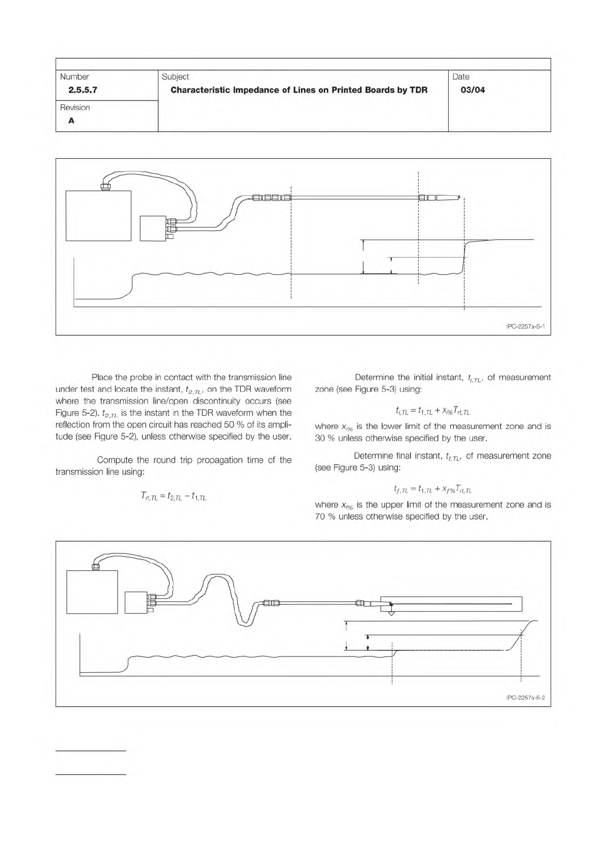
Place
the
probe
in
contact
with
the
transmission
line
under
test
and
locate
the
instant,
t2
TL,
on
the
TDR
waveform
where
the
transmission
line/open
discontinuity
occurs
(see
Figure
5-2).
t2
TL
is
the
instant
in
the
TDR
waveform
when
the
reflection
from
the
open
circuit
has
reached
50
%
of
its
ampli¬
tude
(see
Figure
5-2),
unless
otherwise
specified
by
the
user.
Compute
the
round
trip
propagation
time
of
the
transmission
line
using:
Trt,TL
=
—71
-
力
,71
Determine
the
initial
instant,
tj
TL,
of
measurement
zone
(see
Figure
5-3)
using:
ti,TL
=
力,71
+
Xj%T
也
tl
where
xj%
is
the
lower
limit
of
the
measurement
zone
and
is
30
%
unless
otherwise
specified
by
the
user.
Determine
final
instant,
tf
TU
of
measurement
zone
(see
Figure
5-3)
using:
tf,TL
=
片,几
+xf%Trt,TL
where
xf%
is
the
upper
limit
of
the
measurement
zone
and
is
70
%
unless
otherwise
specified
by
the
user.
IPC-2257a-5-2
Step 1 –
Step 2 –
Step 3 –
Step 4 –
Step 5 –
Figure 5-3 Determination of Measurement Zone
T
rt
,TL
TIME
t
1,TL
t
2,TL
SPD
TRANSFER
STANDARD
TDR
INSTRUMENT
TRANSMISSION LINE UNDER TEST
t
i,TL
t
f,TL
MEASUREMENT ZONE
for TRANSMISSION LINE UNDER TEST
PRECISION
RF CABLE
IPC-TM-650
Page 9 of 23
Number
2.5.5.7
Subject
Characteristic
Impedance
of
Lines
on
Printed
Boards
by
TDR
Date
03/04
Revision
A
5.1.
3.2
Procedure
for
the
Reference
Line
Remove
the
transfer
standard
(or
air
line
reference)
and
hold
the
precision
rf
cable
in
the
air
and
locate
the
instant,
L
Ref,
on
the
TDR
waveform
where
the
rf
cable/open
discon¬
tinuity
occurs
(see
Figure
5-4).
^1Ref
is
the
instant
in
the
TDR
waveform
when
the
reflection
from
the
open
circuit
has
reached
50
%
of
its
amplitude
(see
Figure
5-4),
unless
other¬
wise
specified
by
the
user.
Connect
the
rf
cable
to
the
reference
line
and
locate
the
instant,
t2
Ref,
on
the
TDR
waveform
where
the
reference
line/open
discontinuity
occurs
(see
Figure
5-5).
^‘Ref
is
the
instant
in
the
TDR
waveform
when
the
reflection
from
the
open
circuit
has
reached
50
%
of
its
amplitude
(see
Figure
5-5),
unless
otherwise
specified
by
the
user.
Compute
the
round
trip
propagation
time
of
the
transmission
line
using:
Trt,Ref
=
bkef
-
,Ref
Determine
the
initial
instant,
tiRef,
of
measurement
zone
using:
L,Ref
—
^1
,Ref
+
X/%7^,Aef
where
xi%
is
the
lower
limit
of
the
measurement
zone
and
is
30
%
unless
otherwise
specified
by
the
user.
Determine
final
instant,
tf
TL,
of
measurement
zone
using:
tf,Ref
=
t[Ref
+
XfT^rt.Ref
where
x
侠
is
the
upper
limit
of
the
measurement
zone
and
is
70
%
unless
otherwise
specified
by
the
user.
5.2
Single-Ended
TDR
Measurement
Procedures
This
section
contains
three
methods
for
measuring
the
character¬
istic
impedance
of
single-ended
transmission
lines.
The
fol¬
lowing
calibration
and
measurement
steps
should
be
used
when
the
device(s)
under
test
are
unbalanced
(single-ended)
transmission
lines.
This
process
can
be
followed
manually
but,
to
improve
measurement
repeatability
and
reduce
measure¬
ment
time,
an
automated
measurement
system
is
recom¬
mended.
Additionally,
the
use
of
a
fixture
based
or
robotic
probing
system
greatly
improves
the
accuracy
and
repeatabil¬
ity
over
hand
probe
techniques
and
further
reduces
the
mea¬
surement
time.
5.2.1
Transfer
Standard
Method
In
this
method,
the
impedance
of
the
reference
air
line
is
transferred
to
a
second¬
ary
transmission
line.
The
computed
impedance
of
the
sec¬
ondary
or
transfer
line
then
becomes
the
basis
from
which
the
characteristic
impedance
of
all
subsequent
test
transmission
lines
is
computed.
The
transfer
method
provides
a
direct
com¬
parison
of
the
impedance
of
the
transfer
standard
to
that
of
the
transmission
line
under
test.
Although
this
does
require
two
additional
measurements,
as
compared
to
the
in-situ
method
(see
5.2.2),
it
does
reduce
the
risk
of
damage
to
the
reference
impedance
standard
due
to
frequent
use
and
han¬
dling.
The
effects
of
drift
in
TDR
amplitude
offset
are
mini¬
mized
with
this
method.
5.2.1.
1
Measurement
Calibration
Procedure
The
instru¬
ment
setting
must
be
the
same
for
Steps
1
and
2.
This
pro¬
cedure
will
determine
the
characteristic
impedance
of
the
transfer
standard
from
which
characteristic
impedance
of
the
transmission
line
under
test
will
be
determined
(see
5.2.1
.2).
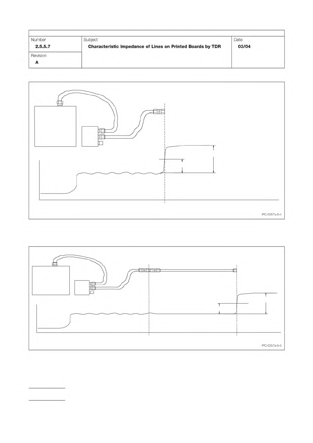
Figure 5-4 Determination of instant in the TDR waveform corresponding to the beginning of the reference line. A
R,0
is the
amplitude of the signal reflected from the open end of rf cable.
SPD
TDR
INSTRUMENT
PRECISION
RF CABLE
t
1,Ref
TIME
0.5
A
R.0
A
R,0
Figure 5-5 Determination of instant in TDR waveform corresponding to the end of the reference line (transfer standard or
air line reference).
A
R,0
is the amplitude of the signal reflected from the open end of the reference line.
SPD
TDR
INSTRUMENT
PRECISION
RF CABLE
t
1,Ref
TIME
0.5
A
R,0
A
R,0
REFERENCE LINE
t
2,Ref
IPC-TM-650
Page 10 of 23
Number
2.5.5.7
Subject
Characteristic
Impedance
of
Lines
on
Printed
Boards
by
TDR
Date
03/04
Revision
A