IPC-TM-650 EN 2022 试验方法--.pdf - 第485页
Step 2 – Step 3 – Figure 5-14 Measurement Zones for Dif ferential TDR -0.4 -0.3 -0.2 -0.1 0.0 0.1 0.2 0.3 0.4 Time Signal (V) Ch1 Ch2 TDR/Probe Interface Probe/T ransmission Line Interface T ransfer Standard Measurement …
Step 1 –
Figure 5-13 Differential TDR Waveform
-0.4
-0.3
-0.2
-0.1
0.0
0.1
0.2
0.3
0.4
Time
Signal (V)
Ch1
Ch2
Transmission Line
Measurement Zone
t
i
t
f
IPC-TM-650
Page 16 of 23
Number
2.5.5.7
Subject
Characteristic
Impedance
of
Lines
on
Printed
Boards
by
TDR
Date
03/04
Revision
A
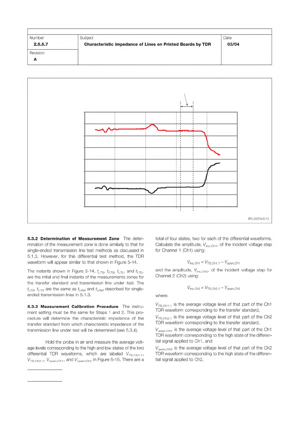
5.3.2
Determination
of
Measurement
Zone
The
deter¬
mination
of
the
measurement
zone
is
done
similarly
to
that
for
single-ended
transmission
line
test
methods
as
discussed
in
5.1
.3.
However,
for
this
differential
test
method,
the
TDR
waveform
will
appear
similar
to
that
shown
in
Figure
5-14.
The
instants
shown
in
Figure
5-14,
ti
TS)
tfTS)
tiTL,
and
tf
TL,
are
the
initial
and
final
instants
of
the
measurements
zones
for
the
transfer
standard
and
transmission
line
under
test.
The
ti
TSf
tf
TS
are
the
same
as
and
tf
Ref
described
for
single-
ended
transmission
lines
in
5.1.3.
5.3.3
Measurement
Calibration
Procedure
The
instru¬
ment
setting
must
be
the
same
for
Steps
1
and
2.
This
pro¬
cedure
will
determine
the
characteristic
impedance
of
the
transfer
standard
from
which
characteristic
impedance
of
the
transmission
line
under
test
will
be
determined
(see
5.3.4).
Hold
the
probe
in
air
and
measure
the
average
volt¬
age
levels
corresponding
to
the
high
and
low
states
of
the
two
differential
TDR
waveforms,
which
are
labeled
\ZTs,ch-\^>
^Ts,ch2,-i>
^open.ch^
Vopen
Ch2
in
Figure
5-15.
There
are
a
total
of
four
states,
two
for
each
of
the
differential
waveforms.
Calculate
the
amplitude,
Vjnc
ChA,
of
the
incident
voltage
step
for
Channel
1
(Ch1)
using:
Vine,
Chi
=
-
Vopen,Ch1
and
the
amplitude,
Vinc
Ch2,
of
the
incident
voltage
step
for
Channel
2
(Ch2)
using:
Vinc,Ch2
=
^TS,Ch2,-\
-
^open,Ch2
where:
Vtssli
is
the
average
voltage
level
of
that
part
of
the
Ch1
TDR
waveform
corresponding
to
the
transfer
standard,
VTS
Ch2
^
is
the
average
voltage
level
of
that
part
of
the
Ch2
TDR
waveform
corresponding
to
the
transfer
standard,
V
open,
chi
is
the
average
voltage
level
of
that
part
of
the
Ch1
TDR
waveform
corresponding
to
the
high
state
of
the
differen¬
tial
signal
applied
to
Ch1
,
and
Vopen,ch2
is
the
average
voltage
level
of
that
part
of
the
Ch2
TDR
waveform
corresponding
to
the
high
state
of
the
differen¬
tial
signal
applied
to
Ch2.
Step 2 –
Step 3 –
Figure 5-14 Measurement Zones for Differential TDR
-0.4
-0.3
-0.2
-0.1
0.0
0.1
0.2
0.3
0.4
Time
Signal (V)
Ch1
Ch2
TDR/Probe Interface
Probe/Transmission Line Interface
Transfer Standard
Measurement Zone
T
ransmission Line
Measurement Zone
t
i,TS
t
i,TL
t
f,TL
t
f,TS
IPC-TM-650
Page 17 of 23
Number
2.5.5.7
Subject
Characteristic
Impedance
of
Lines
on
Printed
Boards
by
TDR
Date
03/04
Revision
A
IPC-2257a-5-14
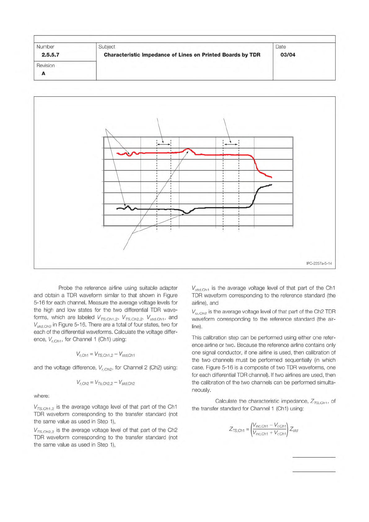
Probe
the
reference
airline
using
suitable
adapter
and
obtain
a
TDR
waveform
similar
to
that
shown
in
Figure
5-16
for
each
channel.
Measure
the
average
voltage
levels
for
the
high
and
low
states
for
the
two
differential
TDR
wave¬
forms,
which
are
labeled
VTSChV2,
VTSiCh2
2,
%内,61,
and
Vstd
Ch2
in
Figure
5-1
6.
There
are
a
total
of
four
states,
two
for
each
of
the
differential
waveforms.
Calculate
the
voltage
differ¬
ence,
“61,
for
Channel
1
(Ch1)
using:
%,C/71
-
^TS,CtT\,2
-
Vstd,Ch1
and
the
voltage
difference,
VrCh2,
for
Channel
2
(Ch2)
using:
^r,Ch2
=
^Ts,Ch2,2
-
^std,Ch2
where:
VTs,chA,2
is
the
average
voltage
level
of
that
part
of
the
Ch1
TDR
waveform
corresponding
to
the
transfer
standard
(not
the
same
value
as
used
in
Step
1),
VTSiCh2
2
is
the
average
voltage
level
of
that
part
of
the
Ch2
TDR
waveform
corresponding
to
the
transfer
standard
(not
the
same
value
as
used
in
Step
1),
VstdChA
is
the
average
voltage
level
of
that
part
of
the
Ch1
TDR
waveform
corresponding
to
the
reference
standard
(the
airline),
and
V/o
Ch2
is
the
average
voltage
level
of
that
part
of
the
Ch2
TDR
waveform
corresponding
to
the
reference
standard
(the
air¬
line).
This
calibration
step
can
be
performed
using
either
one
refer¬
ence
airline
or
two.
Because
the
reference
airline
contains
only
one
signal
conductor,
if
one
airline
is
used,
then
calibration
of
the
two
channels
must
be
performed
sequentially
(in
which
case,
Figure
5-16
is
a
composite
of
two
TDR
waveforms,
one
for
each
differential
TDR
channel).
If
two
airlines
are
used,
then
the
calibration
of
the
two
channels
can
be
performed
simulta¬
neously.
Calculate
the
characteristic
impedance,
ZTSCh-^y
of
the
transfer
standard
for
Channel
1
(Ch1)
using:
7
(Vjnc,Ch1
-
^r.ChA
T
々
s,
cm
二
7^7
^std
yinc.Chl
+
vr,Ch1
j
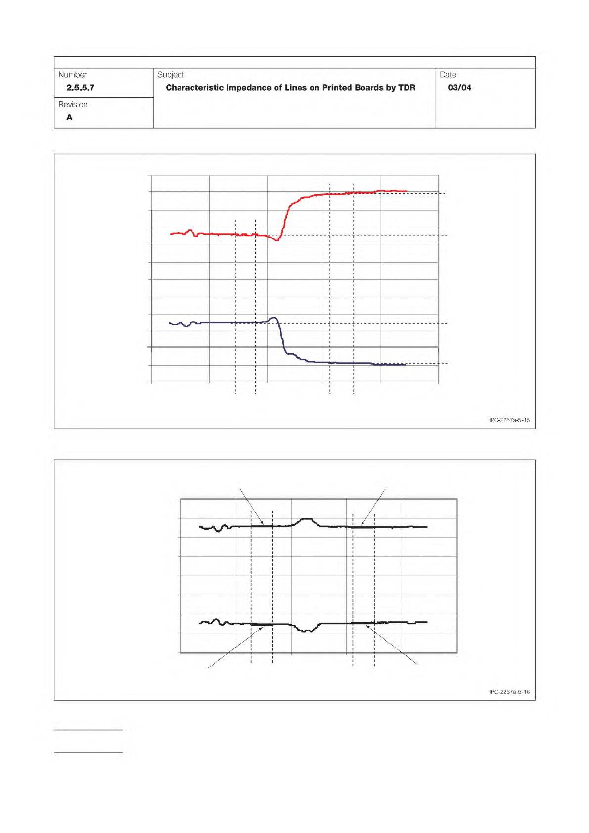
Figure 5-15 Measuring Amplitude for Incident Step
-0.4
-0.3
-0.2
-0.1
0.0
0.1
0.2
0.3
0.4
Signal (V)
Time
t
i,TS
t
f,TS
V
open,Ch1
V
open,Ch
2
Ch1
Ch2
V
TS,Ch2,1
V
TS,Ch1,1
-0.5
-0.6
t
i,TL
t
f,TL
0.5
0.6
Figure 5-16 Calibration of Transfer Standard
-0.4
-0.3
-0.2
-0.1
0.0
0.1
0.2
0.3
0.4
Signal (V)
Time
V
TS,Ch2,2
V
TS,Ch1,2
t
i,TS
t
i,std
t
f,std
t
f,TS
Ch1
Ch2
V
std,Ch1
V
std,Ch2
IPC-TM-650
Page 18 of 23
Number
2.5.5.7
Subject
Characteristic
Impedance
of
Lines
on
Printed
Boards
by
TDR
Date
03/04
Revision
A
IPC-2257a-5-16