IPC-TM-650 EN 2022 试验方法--.pdf - 第56页
5.4.3.1 Rough Polish Rough polish (6 - 3 µm [236 -118 µ in ]) t he s pe c im en u si n g a h a rd , l ow , or n o n a p c l ot h. Reduced wheel speeds are generally use d during final polish- ing due to the increased dra…
5.4.1 Grinding Method A
5.4.1.1 Rough Grinding
Rough grind the mount prior to
the feature intended to be evaluated with abrasive medium.
Wheel speeds of 200 to 300 rpm are generally used during
grinding.
Rotate the specimen 90° between each successive grit size
and grind for two to three times the time it takes to remove
the scratches from the previous step. The scratch removal
can be verified by microscopic inspection between steps. It is
of great importance that the ground surface of the microsec-
tion is in a single plane. The purpose of rotating the microsec-
tion 90° between successive grit sizes is to facilitate
inspection. If scratches are observed to be perpendicular to
those made during the last step performed, it is a good indi-
cation that the surface is not flat and the microsection requires
additional grinding. If the surface of the microsection is not flat
upon completion of the grinding operations, it may not be
possible to remove all of the grinding scratches during fine
grinding.
Caution: Copious water flow must be used to prevent over-
heating, damage to the specimen, and removal of grinding
debris on all grinding steps.
5.4.1.2 Fine Grinding
The final abrasive medium (ANSI
600 grit/P1200 FEPA) should finish at the axial centerline of
the intended feature to be evaluated, such as the plated
structure.
5.4.2 Grinding Method B
5.4.2.1 Tooling Stops
The mount holder has tooling stops
to allow the equipment to grind a set distance. These stops
must be calibrated for each abrasive paper grit to assure that
any scratches from the previous step are removed. See IPC-
MS-810 for a detailed discussion and examples.
5.4.2.2 Grind Pressure
The equipment’s pressure setting
is the direct force on a load cell. To determine the pressure on
each mount, divide the pressure setting by the surface area of
the mounts being processed. See IPC-MS-810 for a detailed
discussion and examples.
The recommended pressure setting for six mounts at 38.1
mm [1.5 in] diameter is 351.5 g/sq. cm (5.0 psi) with the wheel
rotation between 300 - 600 RPM.
5.4.2.3 Other Variables
Recommended variables to be
familiar with are length of time the abrasive paper removes
material efficiently, scratch size the abrasive paper causes on
the specimen(s) surface, and water quality (undissolved par-
ticles that can cause scratches; i.e., calcium deposits).
5.4.2.4 Grind the Mounts
Be liberal with the amount of
water used to promote efficient removal of material by the
abrasive paper. The hardness of the specimen will dictate the
number of rough and fine grind steps needed to reach near
the center of the hole. The rough grind grits ANSI 180-240
(P180 - P240 FEPA) are used to enter the edge of the PTH,
and the fine grind grits ANSI 400-600 (P800-P1200 FEPA) are
used to grind near the center of the hole. The distance to stop
short of the center is determined by the scratch size of the last
grind step used.
A recommended grinding process from which to start devel-
opment is provided in Table 5-2.
5.4.2.5 Clean the Mounts
Clean the mount surface with a
mild hand soap to remove the abrasive grit. This is especially
important when the same mount holder is used for grinding
and polishing. Be careful not to scratch the surfaces to be
evaluated while cleaning.
5.4.3 Polish
The diamond polish media is preferred for
printed boards. Diamond media substantially reduces the risk
of metal smear and rounding. Diamonds provide a sharper
definition of copper surfaces to evaluate for separation of con-
ductive surfaces.
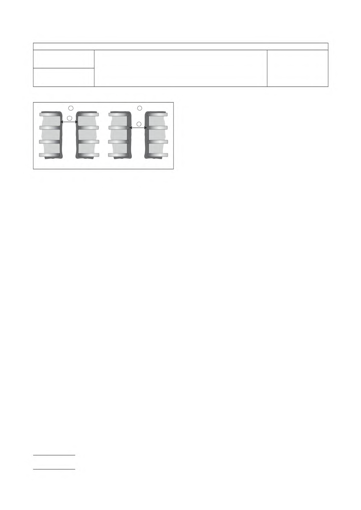
IPC-211-5-2.eps
Figure 5-2 Plated Hole Microsection (Grinding/Polishing)
Tolerance
Note 1. Measurement Example with a Negative Etchback
Process
Note 2. Measurement Example with an Etchback/Desmear
Process
Note 3. Center of Hole Measurement Location
Note 4. Minimum Viewing Area Length = Drill Diameter x 0.9
Note 5. Maximum Viewing Area Length = Drill Diameter
2
3
1
3
IPC-TM-650
Number
2.1.1
Subject
Microsectioning, Manual and Semi or Automatic Method
Date
6/15
Revision
F
Page 4 of 8
5.4.3.1 Rough Polish
Rough polish (6 - 3 µm [236 -118
µin]) the specimen using a hard, low, or no nap cloth.
Reduced wheel speeds are generally used during final polish-
ing due to the increased drag on the microsection. Utilize rec-
ommended lubricant for each polishing medium. Following
rough polishing, microscopically examine the specimen to
verify removal of all previous grit scratches. Ultrasonically
clean the specimen, if desired.
5.4.3.2 Fine Polish
Continue polishing with 1.0 - 0.25 µm
[39.4 - 118 µin] using a hard, low, or no nap cloth and micro-
scopically examine the specimen to verify the removal of all
the previous scratches.
5.4.3.3 Method B – Polish Process Setup
The tooling
stops are recessed or removed from the mount holder during
polishing. The reason for this is that the polish process
removes a negligible amount of material and will not change
the flatness of the surface. The number of polish steps is
determined by the hardness of the specimen(s), distance to
the center of the hole, and scratch size of the last fine grind
step. There may be multiple intermediate polish steps but only
one final polish step.
5.4.3.4 Method B – Intermediate Polish Steps
The inter-
mediate steps must remove the fine grind scratches and pre-
pare the surface for the final polish step. The recommended
process settings for six mounts at 38.1 mm [1.5 in] diameter
is less than 351.5 g/sq. cm [5.0 PSI], a medium to hard pol-
ish cloth, short nap surface, and low wheel RPM (100-200).
Additional variables that must be considered are volume of
lubricant, lubricant types, abrasive size, abrasive type (dia-
mond or oxide), and process time.
5.4.3.5 Method B – Final Polish the Mounts
The final
polish step removes the scratches from intermediate polishing
and prepares the surface for evaluation. The recommended
process setting for the same surface areas as 5.4.3.4 are a
medium to soft polish cloth, low wheel RPM (100 - 200), and
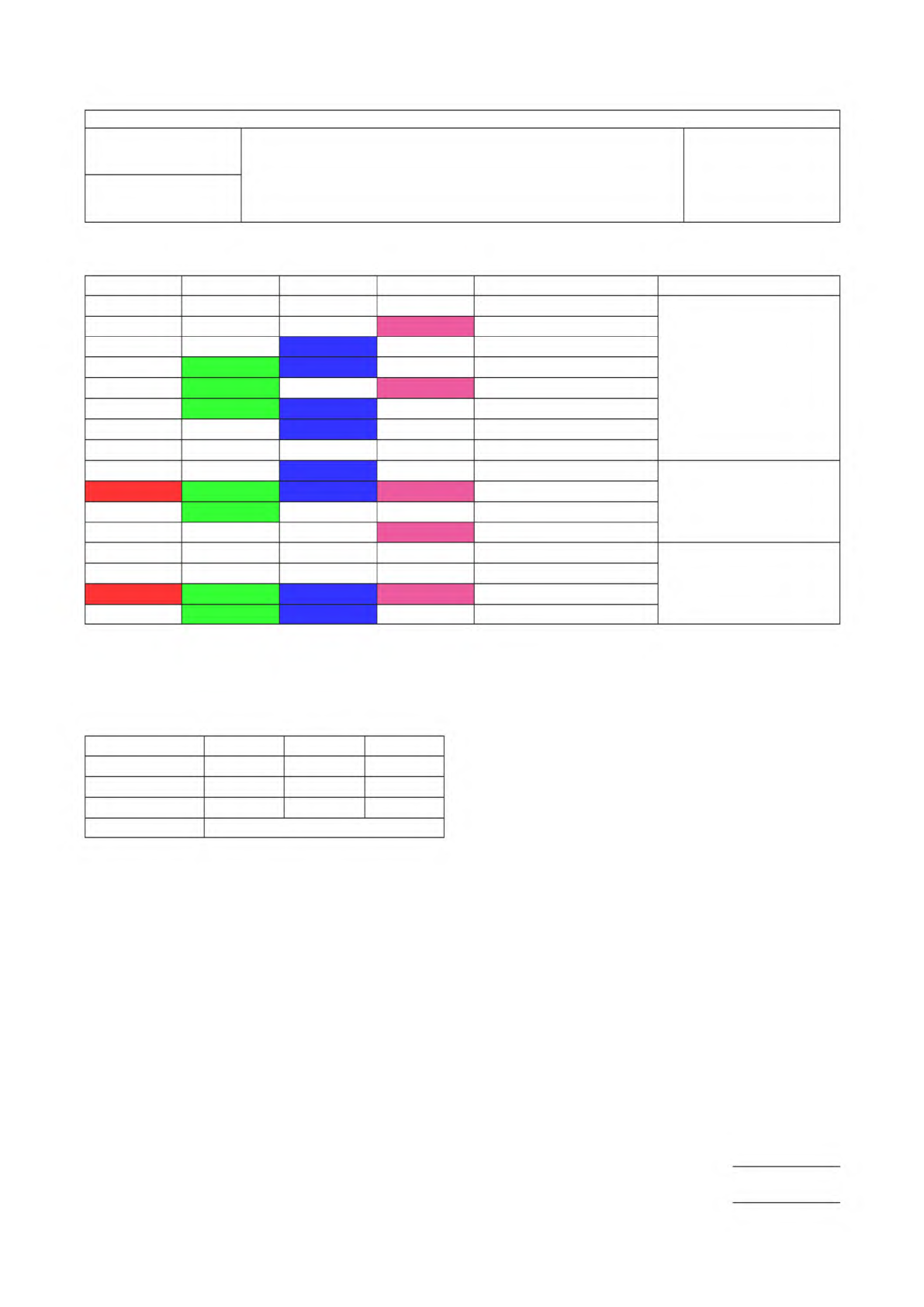
Table 5-1 Suggested Grinding/Polishing Steps – Method A
1,2
2 Step
3
3 Step 4 Step 5 Step Grit ANSI (FEPA)
60 (P60)
Rough Grinding
80 (P80)
120 (P120)
180 (P180)
220 (P220)
240 (P280)
280 (P320)
320 (P320)
400 (P800)
Fine Grinding
600 (P1200)
800 (P2000)
1200 (P4000)
5 micron
Polish
3 micron
1 micron
0.25 Micron
Note 1. The metallographer should recognize the fact that the coarser grit sizes (180, 240, and 320) induce a larger depth of deformed and fragmented material.
Since the depth of deformation decreases sharply below a particle size of about 30.0 µm [1181 µin] (400 grit), it is better practice to spend longer times on
400 grit and especially 600 grit to achieve the final plane sectioning, rather than on the coarser grit sizes.
Note 2. The multiple step method represent ranges that can be used and any one grit size can be used per step.
Note 3. The 2 step process may be used for in-process checks but is not recommended for final acceptance of product.
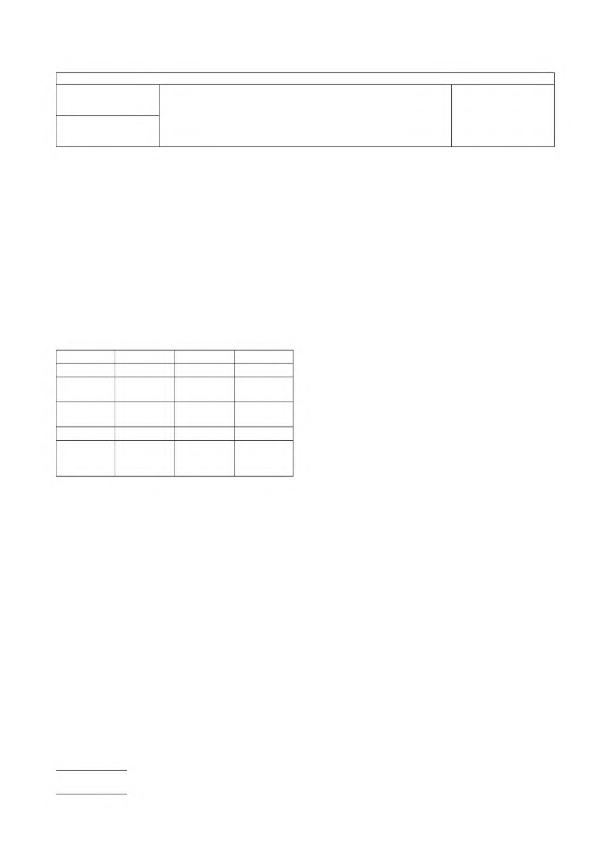
Table 5-2 Recommended Grinding Process – Method B
Step 1 Step 2 Step 3
Abrasive grit size P180 P 400(opt) P1000
RPM 200-300 200-300 200-300
Pressure (g/sq.cm) 351.5 351.5 351.5
Time 15 seconds after the stops touch
IPC-TM-650
Number
2.1.1
Subject
Microsectioning, Manual and Semi or Automatic Method
Date
6/15
Revision
F
Page 5 of 8
low pressure setting 351.5 g/sq. cm [5.0 PSI] or less. Addi-
tional variables that must be considered are volume of lubri-
cant, type of nap surface on polish cloth, and process times.
The type of abrasive used must be diamond (maximum rated
size: 1.0 µm [39.4 µin]) or colloidal silica.
WARNING: If a high nap polish cloth is used too long in the
final polish, the inspectors ability to see defects can be ham-
pered. This step must be engineered for short process times
(30 seconds or less) with a careful balance of lubricant to pre-
vent copper rounding.
A recommended polish process from which to start develop-
ment is provided in Table 5-3.
5.4.3.6
Rinse in mild soap and warm water or IPA and blow
dry.
Caution: Do not touch or wipe surface with anything that
might cause scratches to the polished surface.
5.4.3.7
Examine and repolish, beginning with 6.0 µm [236
µin] diamond, if necessary, until:
1) There are no scratches larger than those induced by the
final polishing abrasive.
2) The specimen is not higher or lower than the mounting
material (rounding of metal surfaces).
3) There is no smearing of the copper plating into the PTH or
base material.
4) The plane of microsectioning is at the centerline of the hole
as defined by the governing specification. If the grinding
depth is insufficient, additional grinding and repolishing
may be required.
5) There is little, if any, visible preparation induced damage to
the glass fibers of the base material.
See IPC-MS-810 for photomicrographs illustrating some of
the above qualities.
5.5 Examination of Microsections
5.5.1 ‘‘As-Polished’’ Condition
When specified, examine
the microsection of multilayer printed boards in the ‘‘as-
polished’’ condition to assess attributes such as internal layer
separation (which may appear as dark lines or partial dark
lines). These areas should be documented prior to microetch-
ing and verified after metallographic etching. There may not be
a one-to-one correlation of all separations noted ‘‘as-
polished’’ versus those noted after etching, when examined at
the specified magnifications.
It is recommended to microetch immediately after the ‘‘as-
polished’’ evaluation to avoid oxidation.
5.5.2 Microetched Condition
Caution: Over etching may totally obscure the demarcation
line between the copper foil and electroplated copper, pre-
venting accurate inspection.
5.5.2.1
Prepare a small volume of copper etch solution
such that:
a) (no more than 10ml) containing 50/50 v/v of ammonium
hydroxide (nominally 28%; grade is not defined) and stabi-
lized hydrogen peroxide (nominally 3%; grade is not
defined). This is the most active concentration and will last
about one hour.
Note: Hydrogen peroxide solution is light sensitive and
should be stored in an opaque container.
b) The addition of 25 ml of water (distilled or reverse osmosis)
will dilute the solution, resulting in longer etching times,
which may be desirable in certain situations. This concen-
tration will have to be remade with each batch.
5.5.2.2
Expose the surface of the microsection to the etch
solution by using one of the following methods:
a) Swab
1) Apply etchant to a swab (outcome based control: no
nonconforming scratches caused by swab).
Table 5-3 Recommended Polishing Process - Method B
Intermediate Final Optional
1
Type of cloth Napless Napless Nap
Type of polish
abrasive
Diamond Diamond Diamond
Polish
abrasive size
3.0 µm
[118 µin]
1.0 µm
[39.4 µin]
1.0 µm
[39.4 µin]
Time — — 30 sec max.
Pressure
(g/sq. cm)
[PSI]
351.5
[5.0 psi] or
less
351.5
[5.0 psi] or
less
351.5
[5.0 psi] or
less
Note 1. When inspecting for innerlayer separations, the optional polish step
shall not be used (see 6.2).
Note 2. Generally, polishing using medium pressure during the above steps is
sufficient if the microsection has been ground correctly. This final
step is only performed for 10 - 20 seconds using light to medium
pressure when using oxide or silica polishing compounds. When
using diamond compounds on soft woven cloths, final polishing may
extend several minutes (see 6.3).
IPC-TM-650
Number
2.1.1
Subject
Microsectioning, Manual and Semi or Automatic Method
Date
6/15
Revision
F
Page 6 of 8