IPC-TM-650 EN 2022 试验方法--.pdf - 第570页
1 Sc op e T he d i el ec tr ic s tr e ng th t es t ( al so c a ll ed hi gh - potential [Hi-Pot], over potential, or voltage breakdown) con- sists of the ap plication of a test voltage for a sp ecific time between mut ual…
IPC-TM-650
Number
Subject Date
Revision
Page 3 of 3
2.5.6
Dielectric
Breakdown
of
Rigid
Printed
Wiring
Material
5/86
B
6.1
The
dielectric
breakdown
of
the
material
may
be
adversely
affected
if
the
drilling
process
used
to
produce
the
holes
is
inadequate.
Use
of
a
sharp
high
speed
drill
is
recom¬
mended
to
prevent
burning
the
material
or
producing
rough
holes.
6.2
This
test
requires
voltages
which
are
life
threatening.
The
High
Voltage
Tester
must
be
installed
and
operated
in
accor¬
dance
with
the
manufacturer's
instructions.
If
the
test
cham¬
ber
is
not
totally
enclosed,
with
a
safety
interlock,
extreme
care
must
be
exercised
in
performance
of
the
test.
1 Scope
The dielectric strength test (also called high-
potential [Hi-Pot], over potential, or voltage breakdown) con-
sists of the application of a test voltage for a specific time
between mutually insulated portions of a printed board or
between insulated portions and ground. This is used to prove
that the printed board can operate safely at its rated voltage
and withstand momentary overpotentials due to switching,
surges, and other similar phenomena.
2 Applicable Documents
Standard Test Method for Dielectric Break-
down Voltage and Dielectric Strength of Solid Electrical Insu-
lation Materials at Commercial Power Frequencies
3 Test Specimen
Three 102 mm x 102 mm [4.016 in x
4.016 in] squares of glass epoxy laminate materials having
1 ounce (0.0343 mm [0.00135 in] nominal) copper foil lami-
nates on one side, and having the test specimen polymer film
applied to the copper surface (see specimen preparation).
4 Apparatus
4.1
Any high voltage potential test equipment capable of
providing voltage increases of 500 VDC per second, up to at
least 10,000 VDC (see Section 6).
4.2
A standard Type 1 electrode per ASTM D 149, with a 51
mm [2.0 in] diameter, 25 mm [1.0 in] thick, with edges
rounded to 6.4 mm [0.25 in.] radius to cover the test surface.
5 Procedure
5.1 Preparation of Test Specimen
5.1.1
Cut the laminate specimen to 102 mm x 102 mm
[4.016 in x 4.016 in] and sand the edges lightly.
5.1.2
If double clad material is used, etch off all copper foil
on one side.
5.1.3
Clean the copper foil surface thoroughly, per the poly-
mer manufacturer’s recommendations, prior to applying poly-
mer coating.
5.1.4
Apply a film of the polymer test material on an area of
76.2 mm x 76.2 mm [3.0 in x 3.0 in] at the center of the cop-
per clad surface. A pinhole free film is essential.
5.1.5
Cure the polymer coating per manufacturer’s recom-
mendations.
5.2 Test
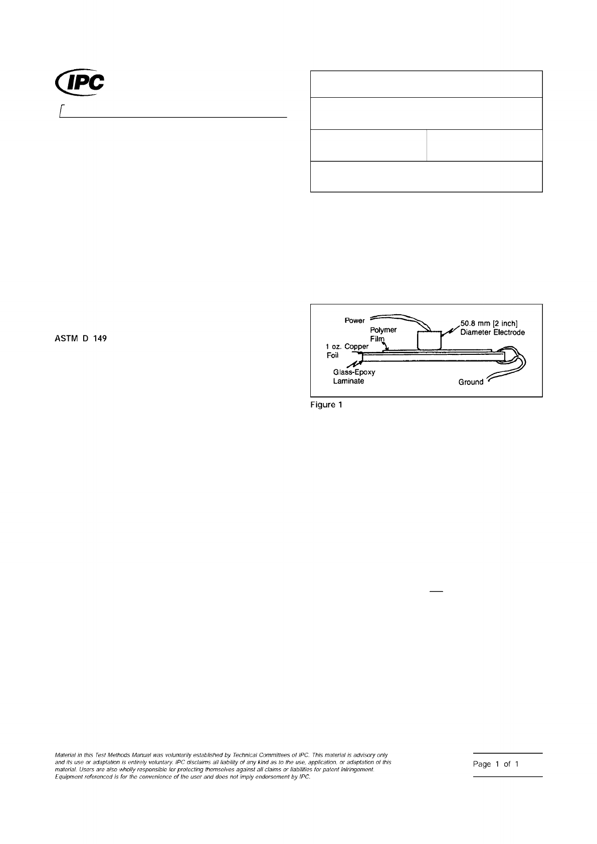
5.2.1
Clip the ground terminal of the tester over the thick-
ness of the copper foil and substrate, being careful not to let
the clip extend inward to the polymer coating (see Figure 1).
5.2.2
Place the positive electrode on top of test panel at the
center. Make certain the electrode and clip are electrically iso-
lated by the test polymer film.
5.2.3
Set up the potential voltage tester. Increase the volt-
age 500 VDC per second, until specimen exceeds require-
ment or breakdown occurs.
5.2.4
Measure the coating thickness of each of the test
specimens to the nearest 0.0025 mm [0.0001 in] in at least
four locations. Compute the average coating thickness and
standard deviation.
5.3 Evaluation
Determine the dielectric strength, E
D
, using:
E
D
=
V
BD
t
where t is the thickness of the specimen, to the nearest
0.0025 mm [0.0001 in], measured in 5.2.4 and V
BD
is
the breakdown voltage measured in 5.2.3. Record results as
‘‘V/mm’’ or ‘‘V/in.’’
6 Notes
6.1
Suggested source for tester: Hipotronics Model HD-140
from Hipotronics, Inc. Brewster, NY 10509, or equivalent.
6.2
Safety must be exercised because of the potential dan-
ger of electrical shock.
IPC-2561-1
3000 Lakeside Drive, Suite 309S
Bannockburn, IL 60015-1249
IPC-TM-650
TEST METHODS MANUAL
Number
2.5.6.1
Subject
Solder Mask - Dielectric Strength
Date
03/07
Revision
B
Originating Task Group
Solder Mask Performance Task Group (5-33b)
ASSOCIATION CONNECTING
ELECTRONICS INDUSTRIES
®
ASTM
D
149
Figure
1
Material
M
this
历
sf
Methods
Manual
was
voluntarily
established
by
Technical
Committees
of
IPC.
This
material
is
advisory
only
and
its
use
。厂
adaptation
is
entirely
voluntary.
IPC
disclaims
liability
of
any
k/nd
as
to
the
use,
application,
or
adaptation
of
this
material.
Users
are
also
wholly
responsible
for
protecting
themselves
against
claims
or
liabililies
for
patent
infringement.
Equipment
referenced
/s
for
the
convenience
of
the
user
and
does
not
imply
endorsement
by
IPC.
Page
1
of
1
ASTM D149
The Institute for Interconnecting and Packaging Electronic Circuits
2215 Sanders Road • Northbrook, IL 60062
Material in this Test Methods Manual was voluntarily established by Technical Committees of the IPC. This material is advisory only
and its use or adaptation is entirely voluntary. IPC disclaims all liability of any kind as to the use, application, or adaptation of this
material. Users are also wholly responsible for protecting themselves against all claims or liabilities for patent infringement.
Equipment referenced is for the convenience of the user and does not imply endorsement by the IPC.
Page 1 of 3
IPC-TM-650
TEST
METHODS
MANUAL
1
.0
Scope
This
method
describes
a
technique
for
evaluat¬
ing
the
ability
of
an
insulating
material
to
resist
electrical
break¬
down
perpendicular
to
the
plane
of
the
material
when
sub¬
jected
to
short
term,
high
voltages
at
standard
AC
power
frequencies
of
50-60
Hz.
1.1
Applicability
and
Use
of
Data
This
method
may
be
used
on
material
of
any
thickness
up
to
approximately
0.125
inch,
however,
for
material
over
0.020
inch,
other
methods
such
as
dielectric
breakdown
are
normally
used
to
character¬
ize
a
material's
electrical
integrity.
Results
of
this
test
may
be
drastically
affected
by
moisture
content,
and
results
obtained
using
different
preconditioning
may
not
be
comparable.
This
method
uses
an
oil
medium
to
prevent
flashover
on
a
small
specimen
and
results
may
not
be
comparable
to
tests
run
in
air.
Values
obtained
using
this
method
should
not
be
used
for
predicting
the
insulating
ability
of
ultra
thin
metal
clad
laminates.
The
values
determined
by
this
method
generally
decrease
with
increasing
specimen
thickness
for
otherwise
identical
material.
This
method
is
based
on
the
techniques
described
in
ASTM
D149.
2
.0
Applicable
Document
Standard
Test
Method
for
Dielectric
Breakdown
Voltage
and
Dielectric
Strength
of
Solid
Electrical
Insulating
Materials
at
Commercial
Power
Frequencies
3
.0
Test
Specimens
3.1
Number
Three
specimens
shall
be
prepared
unless
otherwise
specified.
3.2
Form
Specimens
should
be
4.0
inch
±
1.0
inch
X
4.0
±
1
.0
inch;
however,
size
is
not
critical
as
long
as
no
flashover
occurs
around
the
edges.
Number
2.5.6.2
Subject
Electric
Strength
of
Printed
Wiring
Material
Date
Revision
8/97
A
Originating
Task
Group
N/A
3.3
Location
Specimens
shall
be
cut
by
any
convenient
means
from
both
edges1
and
the
center
of
the
laminate
(except
no
specimen
shall
be
taken
closer
than
1
inch
from
the
edge
of
full
size
sheets).
3.4
Foil
Clad
Material
Foil
clad
materials
shall
have
all
metal
cladding
removed
by
etching
and
should
be
thoroughly
cleaned
prior
to
conditioning
or
testing.
3.5
Uncured
Material
Uncured
material
must
be
fully
cured.
Under
normal
conditions,
two
ply
lamination
is
recom¬
mended
for
comparison
of
prepreg
material.
Single
ply
lami¬
nates
are
recommended
for
cover
lays
and
similar
products
designed
for
single
ply
usage.
4
.0
Apparatus/Materials
4.1
High
voltage
breakdown
tester,
25
KV,
minimum
with
an
adequate
current
rating2,
a
motorized
control
capable
of
500
volts
per
second
rate
of
rise
and
a
meter
capable
of
indicating
breakdown
voltage
within
5%
over
the
entire
range
of
actual
breakdown
voltages
(generally
1
KV
to
20
KV).
4.2
Oil
tank
filled
with
insulating
oil3.
4.3
Electrode
test
set
2
inch
diameter
electrodes
with
1/4
inch
radius
on
the
edge
of
the
electrodes
and
50
g.
±
2
g.
load
applied
by
the
weight
of
upper
electrode
(in
air).
4.4
Two
high
voltage
test
leads
(leads
rated
in
excess
of
the
tester
voltage
capability
are
recommended).
4.5
Micrometer
capable
of
resolving
at
least
0.0001
inch.
Note:
For
accurate
measurement
of
material
under
0.005
inch
test
accuracy
may
be
severely
limited
by
the
ability
to
measure
the
specimen
accurately.
4.6
Constant
temperature
water
bath,
capable
of
maintain¬
ing
50℃
±
2
℃,
filled
with
distilled
water.
1
.
Edges:
For
a
reinforced
laminate
the
specimens
shall
be
from
opposite
edges
of
the
reinforcement.
2.
Current
capacity:
40
milliamps
is
normally
satisfactory.
3.
Insulating
oil:
Shell
Dial
AX
Insulating
Oil
has
been
found
suitable
for
breakdowns
up
to
100
KV.