IPC-TM-650 EN 2022 试验方法--.pdf - 第586页
Figure 1 Distance from Clips The Institute for Int erconnecting and Packaging E lectronic Circuits 2215 Sanders Road • Northbrook, IL 60062 Material in this T est M ethods Manual was voluntarily establis hed by T echni c…
Example
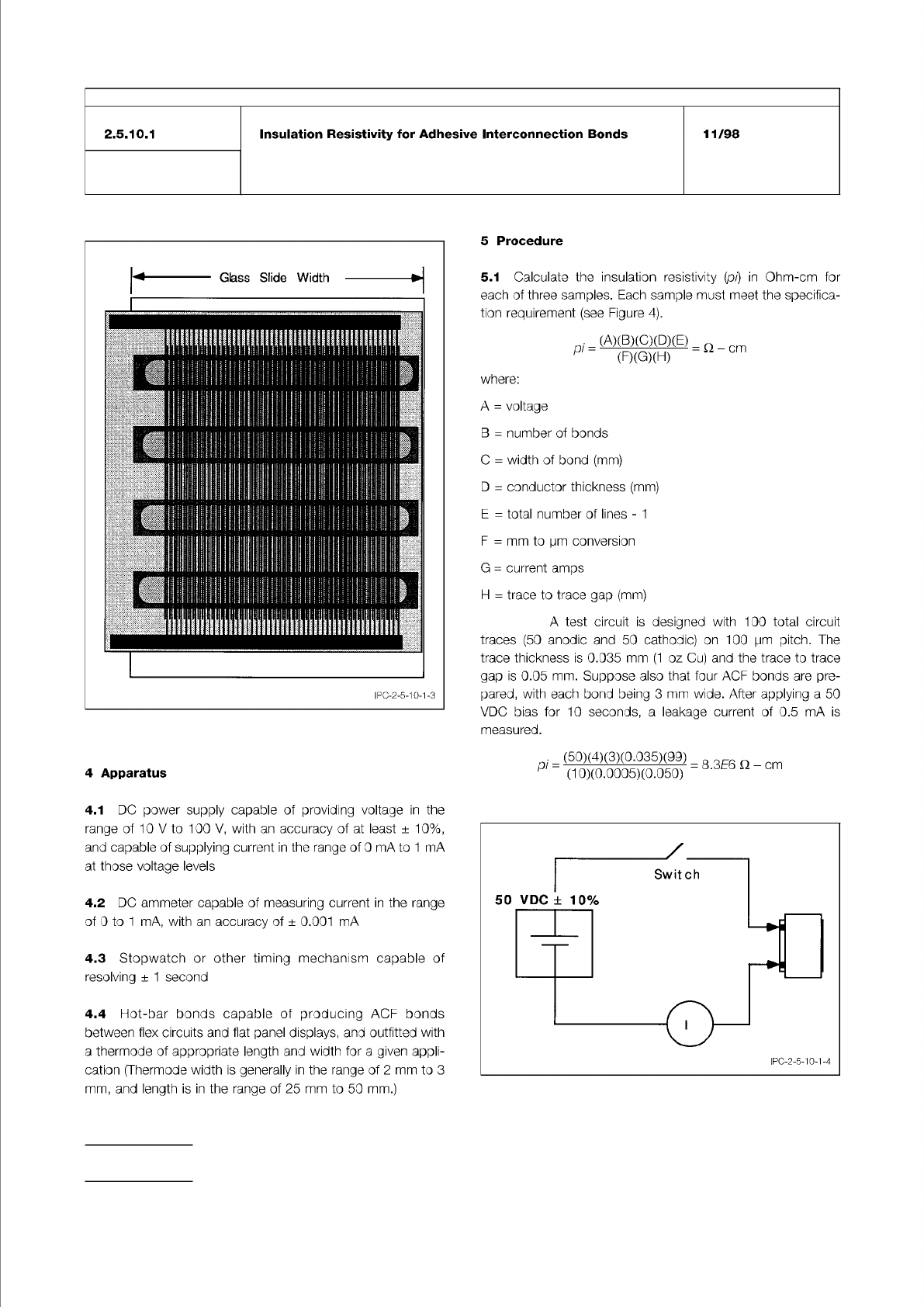
Figure 3 Flex Circuit Containing Four ACF Bond Sites,
After Being Bonded to a Glass Slide
Figure 4 Schematic Diagram for Insulation Resistivity
Measurement
IPC-TM-650
Number
Subject Date
Revision
Page 2 of 2
2.5.10.1
Insulation
Resistivity
for
Adhesive
Interconnection
Bonds
11/98
4
Apparatus
4.1
DC
power
supply
capable
of
providing
voltage
in
the
range
of
1
0
V
to
100
V,
with
an
accuracy
of
at
least
±
10%,
and
capable
of
supplying
current
in
the
range
of
0
mA
to
1
mA
at
those
voltage
levels
4.2
DC
ammeter
capable
of
measuring
current
in
the
range
of
0
to
1
mA,
with
an
accuracy
of
土
0.001
mA
4.3
Stopwatch
or
other
timing
mechanism
capable
of
resolving
±
1
second
4.4
Hot-bar
bonds
capable
of
producing
ACF
bonds
between
flex
circuits
and
flat
panel
displays,
and
outfitted
with
a
thermode
of
appropriate
length
and
width
for
a
given
appli¬
cation
(Thermode
width
is
generally
in
the
range
of
2
mm
to
3
mm,
and
length
is
in
the
range
of
25
mm
to
50
mm.)
5
Procedure
5.1
Calculate
the
insulation
resistivity
(pi)
in
Ohm-cm
for
each
of
three
samples.
Each
sample
must
meet
the
specifica¬
tion
requirement
(see
Figure
4).
where:
(A)(B)(C)(D)(E)
(F)(G)(H)
=
Q
-
cm
A
二
voltage
B
二
number
of
bonds
C
=
width
of
bond
(mm)
D
=
conductor
thickness
(mm)
E
=
total
number
of
lines
-
1
F
=
mm
to
pm
conversion
G
二
current
amps
H
=
trace
to
trace
gap
(mm)
A
test
circuit
is
designed
with
100
total
circuit
traces
(50
anodic
and
50
cathodic)
on
100
pm
pitch.
The
trace
thickness
is
0.035
mm
(1
oz
Cu)
and
the
trace
to
trace
gap
is
0.05
mm.
Suppose
also
that
four
ACF
bonds
are
pre¬
pared,
with
each
bond
being
3
mm
wide.
After
applying
a
50
VDC
bias
for
10
seconds,
a
leakage
current
of
0.5
mA
is
measured.
pi
=
(50)(4)(3)(0.035)(99)
(10)(0.0005)(0.050)
=
8.3E6
Q
-
cm
50
VDC
±
10%
IPC-2-5-10-1-4
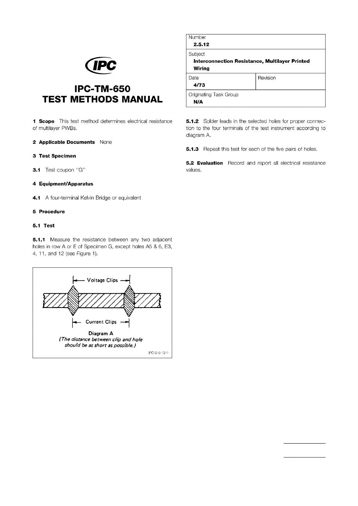
Figure 1 Distance from Clips
The Institute for Interconnecting and Packaging Electronic Circuits
2215 Sanders Road • Northbrook, IL 60062
Material in this Test Methods Manual was voluntarily established by Technical Committees of the IPC. This material is advisory only
and its use or adaptation is entirely voluntary. IPC disclaims all liability of any kind as to the use, application, or adaptation of this
material. Users are also wholly responsible for protecting themselves against all claims or liabilities for patent infringement.
Equipment referenced is for the convenience of the user and does not imply endorsement by the IPC.
Page 1 of 1
回
IPC-TM-650
TEST
METHODS
MANUAL
1
Scope
This
test
method
determines
electrical
resistance
of
multilayer
PWBs.
2
Applicable
Documents
None
3
Test
Specimen
3.1
Test
coupon
"G”
4
Equipment/Apparatus
4.1
A
four-terminal
Kelvin
Bridge
or
equivalent
5
Procedure
5.1
Test
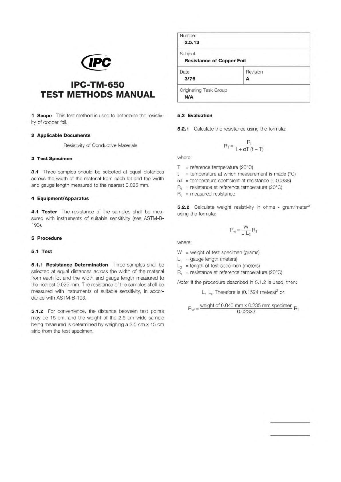
5.1.1
Measure
the
resistance
between
any
two
adjacent
holes
in
row
A
or
E
of
Specimen
G,
except
holes
A5
&
6,
E3,
4,
11
,
and
12
(see
Figure
1).
Diagram
A
(The
distance
between
dip
and
hole
should
be
as
short
as
possible.)
Number
2.5.12
Subject
Interconnection
Resistance,
Multilayer
Printed
Wiring
Date
Revision
4/73
Originating
Task
Group
N/A
5.1.2
Solder
leads
in
the
selected
holes
for
proper
connec¬
tion
to
the
four
terminals
of
the
test
instrument
according
to
diagram
A.
5.1.3
Repeat
this
test
for
each
of
the
five
pairs
of
holes.
5.2
Evaluation
Record
and
report
all
electrical
resistance
values.
I
PC-2-5-1
2-1
ASTM-B-193
The Institute for Interconnecting and Packaging Electronic Circuits
2215 Sanders Road • Northbrook, IL 60062
Material in this Test Methods Manual was voluntarily established by Technical Committees of the IPC. This material is advisory only
and its use or adaptation is entirely voluntary. IPC disclaims all liability of any kind as to the use, application, or adaptation of this
material. Users are also wholly responsible for protecting themselves against all claims or liabilities for patent infringement.
Equipment referenced is for the convenience of the user and does not imply endorsement by the IPC.
Page 1 of 1
IPC-TM-650
TEST
METHODS
MANUAL
1
Scope
This
test
method
is
used
to
determine
the
resistiv¬
ity
of
copper
foil.
2
Applicable
Documents
Resistivity
of
Conductive
Materials
3
Test
Specimen
3.1
Three
samples
should
be
selected
at
equal
distances
across
the
width
of
the
material
from
each
lot
and
the
width
and
gauge
length
measured
to
the
nearest
0.025
mm.
4
Equipment/Apparatus
4.1
Tester
The
resistance
of
the
samples
shall
be
mea¬
sured
with
instruments
of
suitable
sensitivity
(see
ASTM-B-
193).
5
Procedure
5.1
Test
5.1.1
Resistance
Determination
Three
samples
shall
be
selected
at
equal
distances
across
the
width
of
the
material
from
each
lot
and
the
width
and
gauge
length
measured
to
the
nearest
0.025
mm.
The
resistance
of
the
samples
shall
be
measured
with
instruments
of
suitable
sensitivity,
in
accor¬
dance
with
ASTM-B-193.
5.1.2
For
convenience,
the
distance
between
test
points
may
be
15
cm,
and
the
weight
of
the
2.5
cm
wide
sample
being
measured
is
determined
by
weighing
a
2.5
cm
x
1
5
cm
strip
from
the
test
specimen.
Number
2.5.13
Subject
Resistance
of
Copper
Foil
Date
Revision
3/76
A
Originating
Task
Group
N/A
5.2
Evaluation
5.2.1
Calculate
the
resistance
using
the
formula:
Rt
%
=
1
+
aT
(t
-
T)
where:
T
=
reference
temperature
(20℃)
t
二
temperature
at
which
measurement
is
made
(
℃)
aT
二
temperature
coefficient
of
resistance
(0.00388)
Rt
=
resistance
at
reference
temperature
(20℃)
Rt
=
measured
resistance
5.2.2
Calculate
weight
resistivity
in
ohms
-
gram/meter2
using
the
formula:
Pw
=
^Rt
l1l2
where:
W
二
weight
of
test
specimen
(grams)
L
=
gauge
length
(meters)
L2
二
length
of
test
specimen
(meters)
Rt
=
resistance
at
reference
temperature
(20℃)
Note:
If
the
procedure
described
in
5.1
.2
is
used,
then:
L1
L2
Therefore
is
(0.1524
meters)2
or:
p
weight
of
0.040
mm
x
0.235
mm
specimen
门