IPC-TM-650 EN 2022 试验方法--.pdf - 第594页
Figure 1 Shielding Effectiveness T est Setup IPC-TM-650 Number Subject Date Revision Page 4 of 5 10/86 2.5.15 Guidelines and Test Methods for RFI-EMI Shielding of Flat Cable A
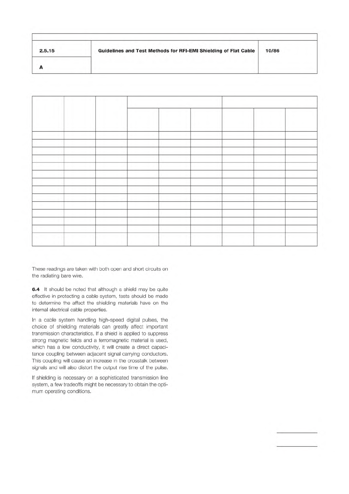
Table 1
Metal
Relative
Conductivity
G
Relative
Permeability
u
Properties
of Various Metals
at 150 KHz
Properties of Various Metals
at 400 MHz
Absorption
Loss in db
A
Magnetic
Reflection
Loss in db
R
H
Electric
Reflection
Loss in db
R
E
Absorption
Loss in db
A
Magnetic
Reflection
Loss in db
R
H
Electric
Reflection
Loss in db
R
E
Silver 1.05 1 1.34 34.7 198.5 6.92 48.9 155.7
Copper 1.00 1 1.31 34.5 198.3 6.76 48.7 155.5
Gold 0.70 1 1.09 32.9 196.7 5.65 47.1 154.0
Aluminum 0.61 1 1.02 32.4 196.1 5.28 46.6 153.4
Magnesium 0.38 1 0.80 30.3 194.1 4.17 44.5 151.3
Cadmium 0.23 1 0.63 28.1 191.9 3.24 42.3 149.1
Nickel 0.20 1 0.58 27.5 191.3 3.02 41.7 148.5
Iron 0.17 1,000 17.06 1.07 160.6 88.14 11.8 117.8
Tin 0.15 1 0.50 26.3 190.0 2.62 40.5 147.3
Steel, 1045 0.10 1,000 13.10 0.0001 158.3 67.6 9.8 115.5
Lead 0.08 1 0.37 23.6 187.3 1.91 37.7 144.5
Mu-Metal 0.03 80,000 64.13
*
7.3 134.0 331.17 0.93 91.2
Permalloy 0.03 80,000 64.13
*
7.3 134.0 331.17 0.93 91.2
Stainless
Steel
0.02 1,000 5.85 -1.3 151.3 30.23 4.2 108.5
*
Valid only if incident field does not saturate metal.
Calculations are for a 0.0025 mm thick shield 2.5 cm away from the radiating source.
IPC-TM-650
Number
Subject Date
Revision
Page 3 of 5
2.5.15
Guidelines
and
Test
Methods
for
RFI-EMI
Shielding
of
Flat
Cable
10/86
A
These
readings
are
taken
with
both
open
and
short
circuits
on
the
radiating
bare
wire.
6.4
It
should
be
noted
that
although
a
shield
may
be
quite
effective
in
protecting
a
cable
system,
tests
should
be
made
to
determine
the
affect
the
shielding
materials
have
on
the
internal
electrical
cable
properties.
In
a
cable
system
handling
high-speed
digital
pulses,
the
choice
of
shielding
materials
can
greatly
affect
important
transmission
characteristics.
If
a
shield
is
applied
to
suppress
strong
magnetic
fields
and
a
ferromagnetic
material
is
used,
which
has
a
low
conductivity,
it
will
create
a
direct
capaci¬
tance
coupling
between
adjacent
signal
carrying
conductors.
This
coupling
will
cause
an
increase
in
the
crosstalk
between
signals
and
will
also
distort
the
output
rise
time
of
the
pulse.
If
shielding
is
necessary
on
a
sophisticated
transmission
line
system,
a
few
tradeoffs
might
be
necessary
to
obtain
the
opti¬
mum
operating
conditions.
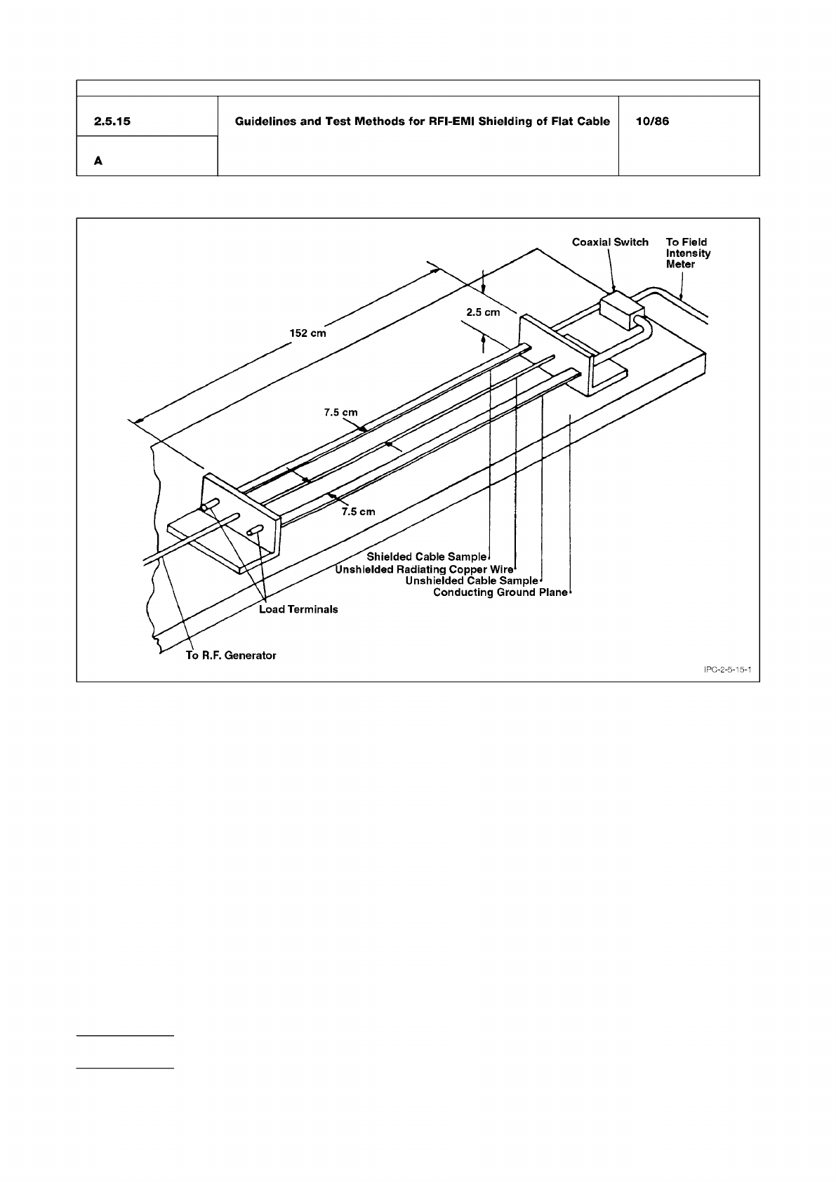
Figure 1 Shielding Effectiveness Test Setup
IPC-TM-650
Number
Subject Date
Revision
Page 4 of 5
10/86
2.5.15
Guidelines
and
Test
Methods
for
RFI-EMI
Shielding
of
Flat
Cable
A
minor
major
IPC-TM-650
Page 3 of 3
Number
2.6.15
Subject
Corrosion,
Flux
Date
06/04
Revision
C
held
for
30
minutes.
The
humidity
should
then
be
increased
to
93%RH.
5.6.3.3
Expose
specimen
to
the
above
environment
for
240
hours
(10
days).
M
and
H
fluxes
may
be
tested
in
the
cleaned,
as
well
as
uncleaned,
condition.
Specimens
shall
be
cleaned
per
the
manufacturers
instructions.
5.7
Evaluation
5.7.1
After
the
exposure
period,
remove
test
specimens
from
humidity
chamber,
examine
at
20X
magnification
and
compare
with
observations
noted
in
6.5
(see
8.2).
5.7.2
For
purposes
of
this
test
method,
the
following
defini¬
tion
of
corrosion
shall
prevail:
"A
chemical
reaction
between
the
copper,
the
solder,
and
the
constituents
of
the
flux
resi¬
dues,
which
occurs
after
soldering
and
during
exposure
to
the
above
environmental
conditions.*
*
Corrosion
for
this
test
is
classified
as
follows:
5.7.2.1
Minor
Corrosion
Any
initial
change
of
color,
which
may
develop
when
the
test
panel
is
heated
during
soldering,
is
disregarded.
Discrete
white
or
colored
spots
in
the
flux
resi¬
dues
or
a
color
change
to
green-blue
without
pitting
of
the
copper
or
formation
of
excrescences
is
regarded
as
corrosion.
5.7.2.2
Major
Corrosion
Any
initial
change
of
color
which
may
develop
when
the
test
panel
is
heated
during
soldering
is
disregarded.
Subsequent
development
of
green-blue
discol¬
oration
with
observation
of
pitting
of
the
copper
panel
or
excrescences
at
the
interfaces
of
the
flux
residue
and
copper
boundary,
is
regarded
as
corrosion.
6
Notes
6・1
Questionable
results
may
be
confirmed
by
analyzing
the
suspected
corrosion
via
Energy
Dispersive
X-ray
Spectros¬
copy
(EDS)
for
the
presence
of
copper.
6.2
Color
photos
before
and
after
the
test
are
valuable
tools
in
identifying
and
documenting
corrosion.
6.3
Safety
Observe
all
appropriate
precautions
on
MSDS
for
chemicals
involved
in
this
test
method.