IPC-TM-650 EN 2022 试验方法--.pdf - 第601页
Note: Note: IPC-TM-650 Number Subject Date Revision Page 4 of 4 2.5.17.1 Volume and Surface Resistivity of Dielectric Materials 12/94 A 5.5 Calculations 5.5.1 The volume resistivity shall be calculated as follows: r = RA…
IPC-TM-650
Page 2 of 2
Number
2.6.16.1
Revision
Subject
Moisture
Resistance
of
High
Density
Interconnection
(HDI)
Materials
Under
High
Temperature
and
Pressure
(Pressure
Vessel)
Date
8/98
5
Procedure
5.1
Prepare
specimens
as
required,
depending
on
the
con¬
figuration
of
the
material
under
test
(see
3.1).
5.2
Preconditioning
The
samples
and
controls
shall
be
dried
by
baking
at
1
05℃
土
2
℃
for
a
minimum
of
two
hours
to
remove
moisture.
5.3
Expose
to
Moisture
Under
Pressure
5.3.1
Place
three
pieces
of
each
type
of
material
to
be
tested
in
the
pressure
vessel,
such
that
they
are
vertical
by
use
of
a
rack
or
grooved
block,
which
does
not
cover
more
than
5%
of
the
surface
area
of
the
specimen.
If
samples
have
been
prepared
as
per
3.
1.2.
2
and
3.1
.3,
place
one
piece
of
the
base
laminate
in
the
vessel
along
with
the
specimens.
5.3.2
Fill
the
pressure
vessel
with
water
such
that
the
speci¬
mens
are
not
sitting
in
the
water.
5.3.3
Close
the
lid
of
the
pressure
vessel
and
seal
the
chamber.
5.3.4
Apply
heat
to
the
pressure
vessel
until
the
temperature
and
pressure
specified
are
attained
and
held
constant.
5.3.5
Water
must
be
replenished
during
the
pressure
vessel
test
to
maintain
the
prescribed
pressure
level.
The
interval
of
replenishment
should
not
be
less
than
six
hours.
5.3.6
After
the
required
time,
which
shall
be
96
hours
unless
otherwise
specified,
remove
the
pressure
cooker
from
the
heat
source
and
open
the
chamber.
Remove
the
specimens
and
lay
on
a
countertop
to
stabilize
at
room
temperature.
5.4
Evaluation
5.4.1
Inspect
the
surface
area
of
the
specimens
using
20/20
vision.
When
applicable,
refer
to
IPC-A-600
to
assess
degra¬
dation,
such
as
measling
or
crazing.
5.4.1.
1
Determine
and
grade
the
presence
of
any
degrada¬
tion
(see
5.5.
1.1
through
5.5.1
.5)
or
other
defects,
such
as
measling,
dryness,
loss
of
surface
resin,
etc.
Use
the
uncon¬
ditioned
specimen
from
each
sample
as
a
control
to
contrast
with
the
conditoned
specimens.
For
samples
prepared
as
per
3.1
.2.2
or
3.1
.3,
use
the
base
laminate
as
control.
5.4.1.
2
Record
any
defects
or
degradation
of
the
material.
Note
the
presence
of
any
defects
in
the
unconditioned
con¬
trol.
Include
the
approximate
number
and
size
of
defects
and
the
total
area
of
the
specimen
surface
that
is
afflicted
with
the
defect(s).
5.4.2
When
required
by
the
procurement
documentation,
microsectioning
shall
be
conducted
as
stated
in
5.421
through
5.4.2.
3.
5.4.2.1
Cross
section
at
least
one
specimen
in
the
center
of
the
specimen
in
accordance
with
Method
2.1
.7.
Mount
a
sec¬
tion
of
the
control
of
that
material
beside
the
conditioned
sec¬
tion.
5.4.2.2
After
polishing
the
sections,
examine
under
100
-
200X.
5.
4.
2.
3
Determine
the
presence
of
voids,
resin-to-
reinforcement
separation,
or
other
defects
in
both
the
control
and
the
conditioned
specimen.
5.5
Report
Report
the
base
thickness
of
the
laminate.
For
prepregs
or
coating
et
al,
if
a
composite
sample
is
fabricated,
include
the
final
thickness
of
the
material
in
question
and
the
thickness
of
the
core
laminate.
5.5.1
Report
the
condition
of
the
specimens
according
to
the
following
grade
system.
If
significant
differences
are
noted
between
specimens
of
one
material,
note
the
worse
condition.
Exclude
the
outer
7
mm.
5.5.1.
1
Grade
5
No
measling,
delamination,
dryness,
void¬
ing
or
other
degradation
in
excess
of
that
observed
on
the
unconditioned
sample.
5.5.1.
2
Grade
4
Very
slight
measling;
or
slight
dryness.
5.5.1.
3
Grade
3
Slight
measling
or
dryness;
or
maximum,
of
three
voids
no
greater
than
0.25
mm.
5.5.1.
4
Grade
2
Moderate
measling
or
dryness;
moderate
dryness;
or
more
than
three
voids
no
greater
than
0.5
mm.
5.5.1.
5
Grade
1
Heavy
measling
and
dryness;
or
voids
greater
than
0.5
mm;
blisters
or
delamination.
5.5.2
Optional
Microsectioning
Evaluation
Report
the
presence
of
defects
in
both
control
and
conditioned
speci¬
mens.
Note:
Note:
IPC-TM-650
Number
Subject Date
Revision
Page 4 of 4
2.5.17.1
Volume
and
Surface
Resistivity
of
Dielectric
Materials
12/94
A
5.5
Calculations
5.5.1
The
volume
resistivity
shall
be
calculated
as
follows:
r
=
RA
T
Where:
r
=
Volume
resistivity
in
megohm-centimeters
R
=
Measured
volume
resistance
in
megohms
A
=
Effective
area
of
the
guarded
electrode
in
square
centi¬
meters
T
=
Average
thickness
of
specimen
in
centimeters
T
=
(t)
x
2.54
[see
5.2.1]
t
=
Average
thickness
(t)
in
inches
(from
5.4)
The
value
of
A
may
be
obtained
from
the
Dimension
Table.
5.5.2
The
surface
resistivity
shall
be
calculated
as
follows:
r1
=
R1P
dT
Where:
r1
=
Surface
resistivity
in
megohms
R1
=
Measured
surface
resistance
in
megohms
P
二
Effective
perimeter
of
the
guarded
electrode
in
centime¬
ters
D4
=
Width
of
the
test
gap
in
centimeters
The
ratio
of
P/D4
for
the
electrode
configuration
being
used
may
be
obtained
from
the
Dimension
Table
included
in
Figure
1
.
5.6
Reporting
5.6.1
The
volume
resistivity
of
each
specimen
and
the
aver¬
age
shall
be
reported.
Each
condition
tested
shall
be
reported
separately.
5.6.2
The
surface
resistivity
of
each
specimen
and
the
aver¬
age
shall
be
reported.
Each
condition
shall
be
reported
sepa¬
rately.
5.6.2.1
The
surface
resistance
is
the
direct
reading
of
the
megohmeter
scale
and
should
be
recorded
in
megohms.
6.0
Notes
6.1
For
additional
information
see
ASTM-D-257,
D-C
Resis¬
tance
or
Conductance
of
Insulating
Materials.
6.2
The
system
of
electrical
connections
to
the
specimens
may
benefit
from
a
coaxial
cable
set-up
designed
to
shield
the
measurement
of
volume
or
surface
resistances
from
electrical
interference.
6.3
Performance
Specifications
The
following
informa¬
tion
should
be
reviewed
within
the
applicable
performance
specification
or
product
procurement
document:
a.
Specimen
size,
quantity,
and
configuration,
if
other
than
that
specified
in
3.0.
b.
Conditioning
parameters,
such
as
temperature
for
Elevated
Temperatures.
c.
Any
other
changes
to
the
specified
procedures
in
this
method.
[
[
IPC-TM-650
[
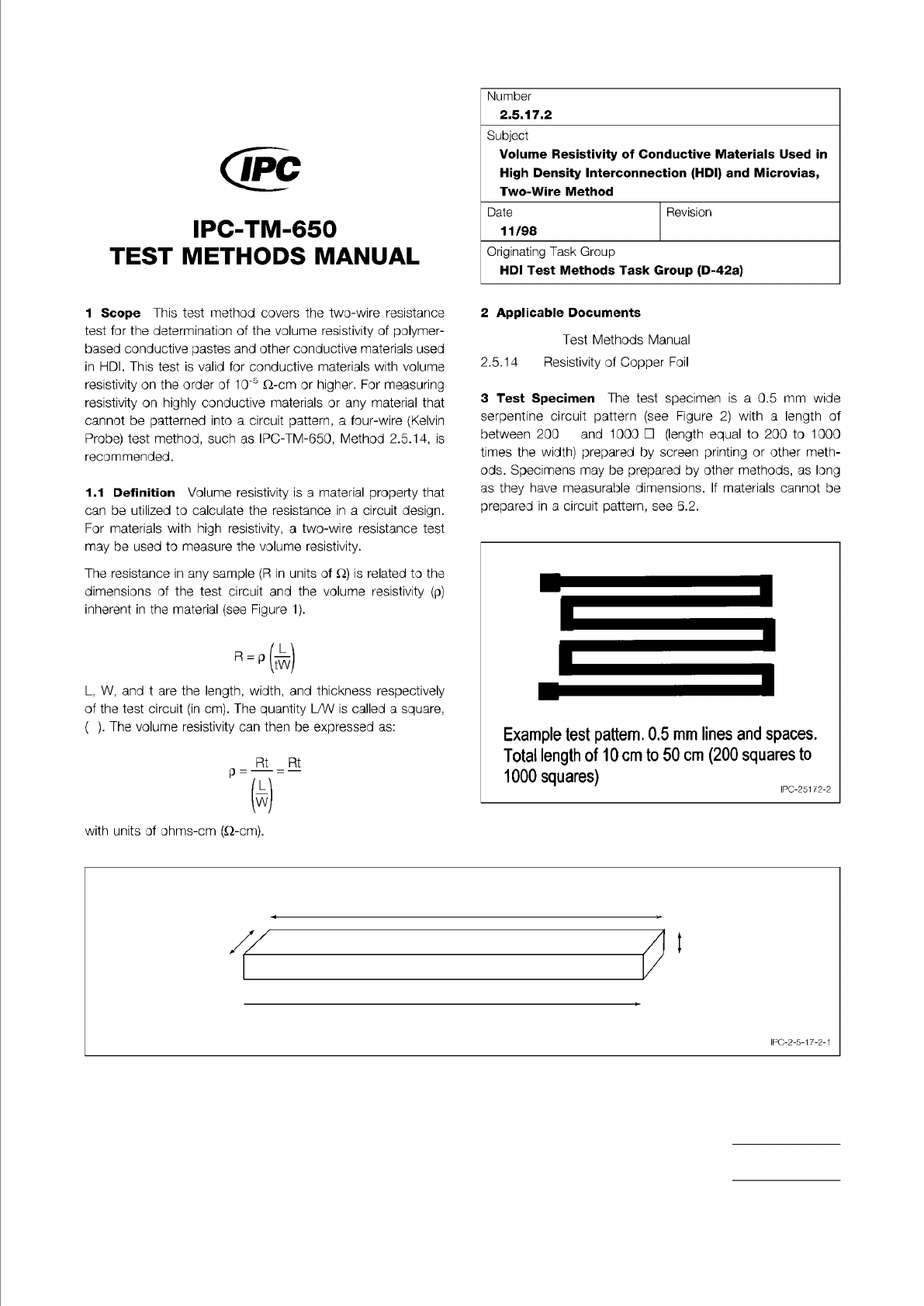
Figure 1 Resistivity Diagram
Conductor
Length = L
Current Flow
Width = W
Thickness = t
Figure 2 Serpentine Pattern
The Institute for Interconnecting and Packaging Electronic Circuits
2215 Sanders Road • Northbrook, IL 60062
Material in this Test Methods Manual was voluntarily established by Technical Committees of the IPC. This material is advisory only
and its use or adaptation is entirely voluntary. IPC disclaims all liability of any kind as to the use, application, or adaptation of this
material. Users are also wholly responsible for protecting themselves against all claims or liabilities for patent infringement.
Equipment referenced is for the convenience of the user and does not imply endorsement by the IPC.
Page 1 of 3
Number
回
IPC-TM-650
TEST
METHODS
MANUAL
1
Scope
This
test
method
covers
the
two-wire
resistance
test
for
the
determination
of
the
volume
resistivity
of
polymer¬
based
conductive
pastes
and
other
conductive
materials
used
in
HDI.
This
test
is
valid
for
conductive
materials
with
volume
resistivity
on
the
order
of
10-5
Q-cm
or
higher.
For
measuring
resistivity
on
highly
conductive
materials
or
any
material
that
cannot
be
patterned
into
a
circuit
pattern,
a
four-wire
(Kelvin
Probe)
test
method,
such
as
IPC-TM-650,
Method
2.5.14,
is
recommended.
1.1
Definition
Volume
resistivity
is
a
material
property
that
can
be
utilized
to
calculate
the
resistance
in
a
circuit
design.
For
materials
with
high
resistivity,
a
two-wire
resistance
test
may
be
used
to
measure
the
volume
resistivity.
The
resistance
in
any
sample
(R
in
units
of
Q)
is
related
to
the
dimensions
of
the
test
circuit
and
the
volume
resistivity
(p)
inherent
in
the
material
(see
Figure
1).
R
=
p
信)
L,
W,
and
t
are
the
length,
width,
and
thickness
respectively
of
the
test
circuit
(in
cm).
The
quantity
L/W
is
called
a
square,
(
).
The
volume
resistivity
can
then
be
expressed
as:
Rt Rt
p
=
—
=—
向
with
units
of
ohms-cm
(Q-cm).
2.5.17.2
Subject
Volume
Resistivity
of
Conductive
Materials
Used
in
High
Density
Interconnection
(HDI)
and
Microvias,
Two-
Wire
Method
Date
11/98
Revision
Originating
Task
Group
HDI
Test
Methods
Task
Group
(D-42a)
2
Applicable
Documents
Test
Methods
Manual
2.5.14
Resistivity
of
Copper
Foil
3
Test
Specimen
The
test
specimen
is
a
0.5
mm
wide
serpentine
circuit
pattern
(see
Figure
2)
with
a
length
of
between
200
and
1000
口
(length
equal
to
200
to
1000
times
the
width)
prepared
by
screen
printing
or
other
meth¬
ods.
Specimens
may
be
prepared
by
other
methods,
as
long
as
they
have
measurable
dimensions.
If
materials
cannot
be
prepared
in
a
circuit
pattern,
see
6.2.
IPC-2-5-1
7-2-1