IPC-TM-650 EN 2022 试验方法--.pdf - 第608页
Figure 5 Connection of Impedance Probe to Sample under T est IPC-TM-650 Number Subject Date Revision Page 4 of 4 7/84 2.5.18 B Characteristic Impedance Flat Cables (Unbalanced) 6 Notes 6.1 The TDR employs a pulse rise ti…
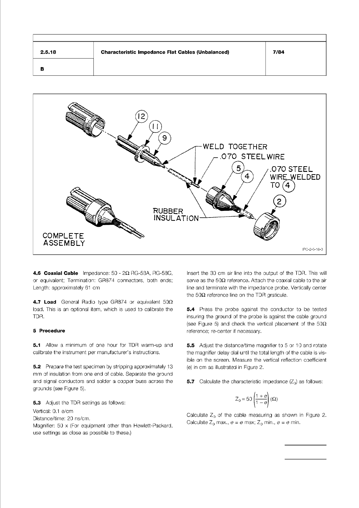
Figure 4 Cable Connection Device. Refer circled items to parts list. Made from General Radio Co. Type 874-C62A.
IPC-TM-650
Number
Subject Date
Revision
Page 3 of 4
2.5.18
Characteristic
Impedance
Flat
Cables
(Unbalanced)
7/84
B
4.6
Coaxial
Cable
Impedance:
50
-
2c
RG-58A,
RG-58C,
or
equivalent;
Termination:
GR874
connectors,
both
ends;
Length:
approximately
61
cm
4.7
Load
General
Radio
type
GR874
or
equivalent
50Q
load.
This
is
an
optional
item,
which
is
used
to
calibrate
the
TDR.
5
Procedure
5.1
Allow
a
minimum
of
one
hour
for
TDR
warm-up
and
calibrate
the
instrument
per
manufacturer's
instructions.
5.2
Prepare
the
test
specimen
by
stripping
approximately
1
3
mm
of
insulation
from
one
end
of
cable.
Separate
the
ground
and
signal
conductors
and
solder
a
copper
buss
across
the
grounds
(see
Figure
5).
5.3
Adjust
the
TDR
settings
as
follows:
Vertical:
0.1
e/cm
Distance/time:
20
ns/cm.
Magnifier:
50
x
(For
equipment
other
than
Hewlett-Packard,
use
settings
as
close
as
possible
to
these.)
Insert
the
30
cm
air
line
into
the
output
of
the
TDR.
This
will
serve
as
the
50Q
reference.
Attach
the
coaxial
cable
to
the
air
line
and
terminate
with
the
impedance
probe.
Vertically
center
the
50Q
reference
line
on
the
TDR
graticule.
5.4
Press
the
probe
against
the
conductor
to
be
tested
insuring
the
ground
of
the
probe
is
against
the
cable
ground
(see
Figure
5)
and
check
the
vertical
placement
of
the
50Q
reference;
re-center
if
necessary.
5.5
Adjust
the
distance/time
magnifier
to
5
or
10
and
rotate
the
magnifier
delay
dial
until
the
total
length
of
the
cable
is
vis¬
ible
on
the
screen.
Measure
the
vertical
reflection
coefficient
(e)
in
cm
as
illustrated
in
Figure
2.
5.7
Calculate
the
characteristic
impedance
(Zo)
as
follows:
1
+
Q
Zo
=
5O
宙
(
Q)
i
y
Calculate
Zo
of
the
cable
measuring
as
shown
in
Figure
2.
Calculate
Zo
max.,
e
=
e
max;
Zo
min.,
e
=
e
min.
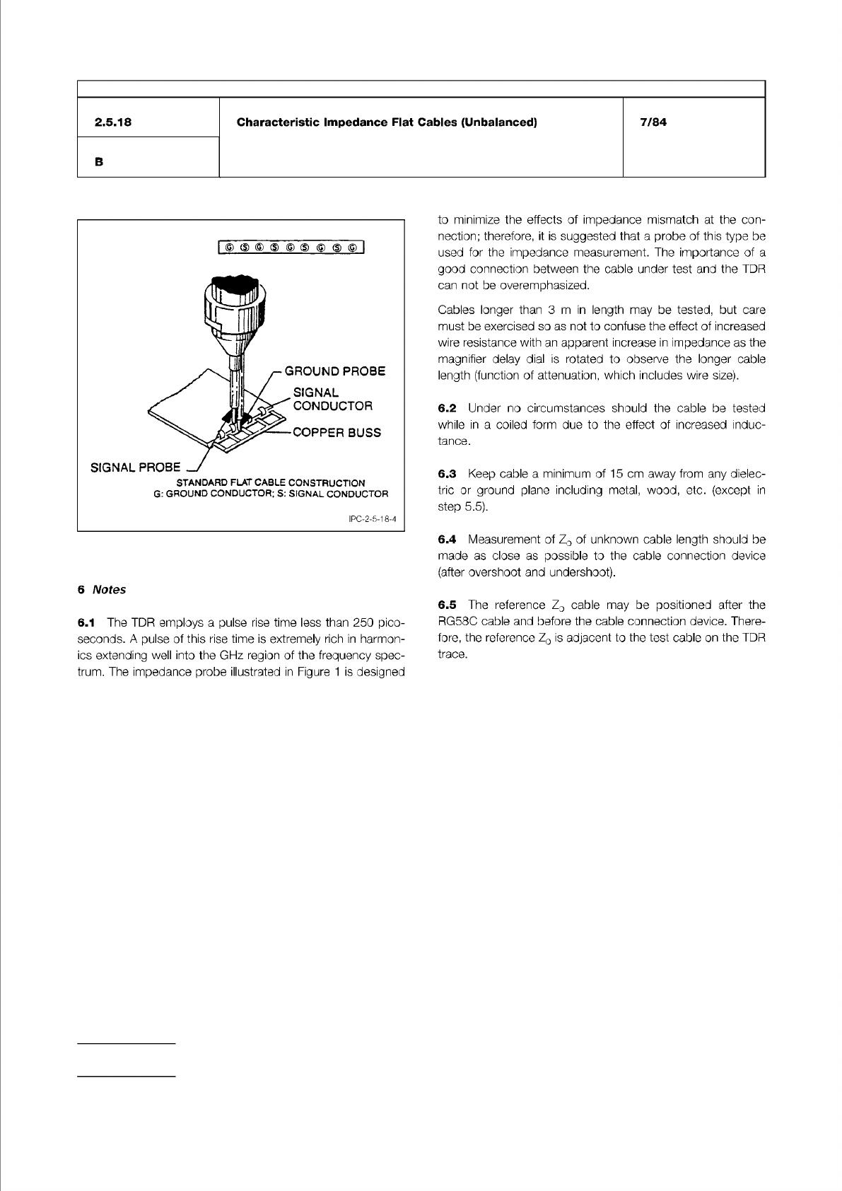
Figure 5 Connection of Impedance Probe to Sample
under Test
IPC-TM-650
Number
Subject Date
Revision
Page 4 of 4
7/84
2.5.18
B
Characteristic
Impedance
Flat
Cables
(Unbalanced)
6
Notes
6.1
The
TDR
employs
a
pulse
rise
time
less
than
250
pico¬
seconds.
A
pulse
of
this
rise
time
is
extremely
rich
in
harmon¬
ics
extending
well
into
the
GHz
region
of
the
frequency
spec¬
trum.
The
impedance
probe
illustrated
in
Figure
1
is
designed
to
minimize
the
effects
of
impedance
mismatch
at
the
con¬
nection;
therefore,
it
is
suggested
that
a
probe
of
this
type
be
used
for
the
impedance
measurement.
The
importance
of
a
good
connection
between
the
cable
under
test
and
the
TDR
can
not
be
overemphasized.
Cables
longer
than
3
m
in
length
may
be
tested,
but
care
must
be
exercised
so
as
not
to
confuse
the
effect
of
increased
wire
resistance
with
an
apparent
increase
in
impedance
as
the
magnifier
delay
dial
is
rotated
to
observe
the
longer
cable
length
(function
of
attenuation,
which
includes
wire
size).
6.2
Under
no
circumstances
should
the
cable
be
tested
while
in
a
coiled
form
due
to
the
effect
of
increased
induc¬
tance.
6.3
Keep
cable
a
minimum
of
1
5
cm
away
from
any
dielec¬
tric
or
ground
plane
including
metal,
wood,
etc.
(except
in
step
5.5).
6.4
Measurement
of
Zo
of
unknown
cable
length
should
be
made
as
close
as
possible
to
the
cable
connection
device
(after
overshoot
and
undershoot).
6.5
The
reference
Zo
cable
may
be
positioned
after
the
RG58C
cable
and
before
the
cable
connection
device.
There¬
fore,
the
reference
Zo
is
adjacent
to
the
test
cable
on
the
TDR
trace.
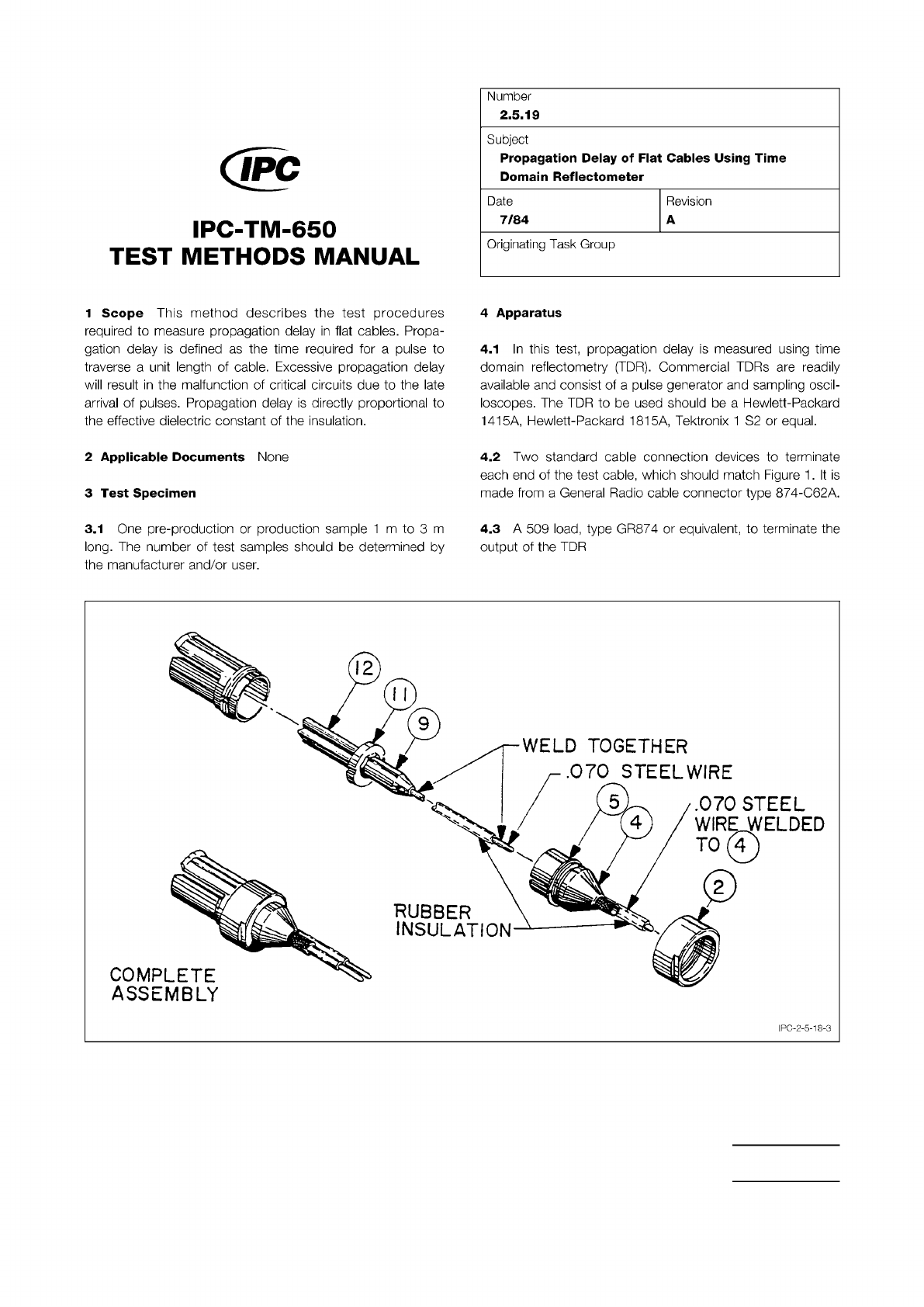
Figure 1 Cable Connection Device
The Institute for Interconnecting and Packaging Electronic Circuits
2215 Sanders Road • Northbrook, IL 60062
Material in this Test Methods Manual was voluntarily established by Technical Committees of the IPC. This material is advisory only
and its use or adaptation is entirely voluntary. IPC disclaims all liability of any kind as to the use, application, or adaptation of this
material. Users are also wholly responsible for protecting themselves against all claims or liabilities for patent infringement.
Equipment referenced is for the convenience of the user and does not imply endorsement by the IPC.
Page 1 of 3
回
IPC-TM-650
TEST
METHODS
MANUAL
1
Scope
This
method
describes
the
test
procedures
required
to
measure
propagation
delay
in
flat
cables.
Propa¬
gation
delay
is
defined
as
the
time
required
for
a
pulse
to
traverse
a
unit
length
of
cable.
Excessive
propagation
delay
will
result
in
the
malfunction
of
critical
circuits
due
to
the
late
arrival
of
pulses.
Propagation
delay
is
directly
proportional
to
the
effective
dielectric
constant
of
the
insulation.
2
Applicable
Documents
None
3
Test
Specimen
3.1
One
pre-production
or
production
sample
1
m
to
3
m
long.
The
number
of
test
samples
should
be
determined
by
the
manufacturer
and/or
user.
Number
2.5.19
Subject
Propagation
Delay
of
Flat
Cables
Using
Time
Domain
Reflectometer
Date
7/84
Revision
A
Originating
Task
Group
4
Apparatus
4.1
In
this
test,
propagation
delay
is
measured
using
time
domain
reflectometry
(TDR).
Commercial
TDRs
are
readily
available
and
consist
of
a
pulse
generator
and
sampling
oscil¬
loscopes.
The
TDR
to
be
used
should
be
a
Hewlett-Packard
1415A,
Hewlett-Packard
1815A,
Tektronix
1
S2
or
equal.
4.2
Two
standard
cable
connection
devices
to
terminate
each
end
of
the
test
cable,
which
should
match
Figure
1
.
It
is
made
from
a
General
Radio
cable
connector
type
874-C62A.
4.3
A
509
load,
type
GR874
or
equivalent,
to
terminate
the
output
of
the
TDR
RUBBER
INSULATION
COMPLETE
ASSEMBLY
.070
STEEL
WIREWELDED
TO
年)
WELD
TOGETHER
.070
STEELWIRE
5
4
12
I
I
I
PC-2-5-1
8-3