IPC-TM-650 EN 2022 试验方法--.pdf - 第61页
Figure 1 Dicy inspection set-up (expanded view) The Institute for Int erconnecting and Packaging E lectronic Circuits 2215 S anders Road • Northbrook, IL 60062-6135 Material in this T est M ethods Manual was vol untaril …
The Institute for Interconnecting and Packaging Electronic Circuits
2215 Sanders Road • Northbrook, IL 60062-6135
Material in this Test Methods Manual was voluntarily established by Technical Committees of the IPC. This material is advisory only
and its use or adaptation is entirely voluntary. IPC disclaims all liability of any kind as to the use, application, or adaptation of this
material. Users are also wholly responsible for protecting themselves against all claims or liabilities for patent infringement.
Equipment referenced is for the convenience of the user and does not imply endorsement by the IPC.
Page 1 of 1
IPC-TM-650
TEST
METHODS
MANUAL
1
.0
Scope
To
visually
locate,
and
by
feel,
evaluate
surface
scratches
during
visual
inspection.
If
more
exacting
data
is
required
for
referee
evaluations
of
microsectioning
per
IPC-TM-650,
Method
2.1
.1
shall
be
used.
2
.0
Applicable
Documents
None.
3
.0
Test
Specimen
Any
qualified
submitted
sheet(s)
or
cut
to
size
panel(s)
or
periodic
quality
conformance
specimens.
4
.0
Apparatus
Dunlop
Tortex
guitar
pick
1
.00
mm
thick¬
ness
or
equivalent.
5
.0
Procedures
5.1
Test
Number
2.1.9
Subject
Surface
Scratch
Examination
Metal-Clad
Foil
Date
Revision
5/86
Originating
Task
Group
N/A
5.1.1
Locate
scratches
visually
using
normal
or
corrected
20/20
vision.
5.1.2
Scratches
which
stop
the
pick
when
light
pressure
is
applied
are
unacceptable.
Scratches
which
can
be
felt
by
the
pick
but
do
not
stop
it
are
acceptable.
5.1.3
The
referee
test
shall
be
by
microsection
per
IPC-TM-
650,
Method
2.1.1.
5.2
Evaluation
5.2.1
Evaluate
in
the
“working
area”
of
the
sheet
or
panel.
Working
area
excludes
a
1
in.
border
on
all
four
edges.
Compare
results
with
inspection
represented
in
the
appropri¬
ate
specification.
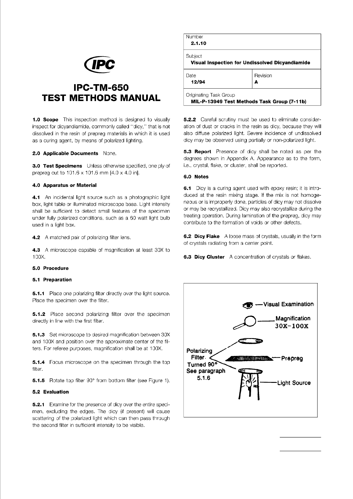
Figure 1 Dicy inspection set-up (expanded view)
The Institute for Interconnecting and Packaging Electronic Circuits
2215 Sanders Road • Northbrook, IL 60062-6135
Material in this Test Methods Manual was voluntarily established by Technical Committees of the IPC. This material is advisory only
and its use or adaptation is entirely voluntary. IPC disclaims all liability of any kind as to the use, application, or adaptation of this
material. Users are also wholly responsible for protecting themselves against all claims or liabilities for patent infringement.
Equipment referenced is for the convenience of the user and does not imply endorsement by the IPC.
Page 1 of 3
IPC-TM-650
TEST
METHODS
MANUAL
1
.0
Scope
This
inspection
method
is
designed
to
visually
inspect
for
dicyandiamide,
commonly
called
lidicy,"
that
is
not
dissolved
in
the
resin
of
prepreg
materials
in
which
it
is
used
as
a
curing
agent,
by
means
of
polarized
lighting.
2
.0
Applicable
Documents
None.
3
.0
Test
Specimens
Unless
otherwise
specified,
one
ply
of
prepreg
cut
to
101
.6
x
1
01
.6
mm
[4.0
x
4.0
in].
4
.0
Apparatus
or
Material
4.1
An
incidental
light
source
such
as
a
photographic
light
box,
light
table
or
illuminated
microscope
base.
Light
intensity
shall
be
sufficient
to
detect
small
features
of
the
specimen
under
fully
polarized
conditions,
such
as
a
60
watt
light
bulb
used
in
a
light
box.
4.2
A
matched
pair
of
polarizing
filter
lens.
4.3
A
microscope
capable
of
magnification
at
least
30X
to
100X.
5
.0
Procedure
5.1
Preparation
5.1.1
Place
one
polarizing
filter
directly
over
the
light
source.
Place
the
specimen
over
the
filter.
5.1.2
Place
second
polarizing
filter
over
the
specimen
directly
in
line
with
the
first
filter.
5.1.3
Set
microscope
to
desired
magnification
between
30X
and
100X
and
position
over
the
approximate
center
of
the
fil¬
ters.
For
referee
purposes,
magnification
shall
be
at
100X.
5.1.4
Focus
microscope
on
the
specimen
through
the
top
filter.
5.1.5
Rotate
top
filter
90°
from
bottom
filter
(see
Figure
1).
5.2
Evaluation
5.2.1
Examine
for
the
presence
of
dicy
over
the
entire
speci¬
men,
excluding
the
edges.
The
dicy
(if
present)
will
cause
scattering
of
the
polarized
light
which
can
then
pass
through
the
second
filter
in
sufficient
intensity
to
be
visible.
Number
2.1.10
Subject
Visual
Inspection
for
Undissolved
Dicyandiamide
Date
12/94
Revision
A
Originating
Task
Group
MIL-P-13949
Test
Methods
Task
Group
(7-1
1b)
5.2.2
Careful
scrutiny
must
be
used
to
eliminate
consider¬
ation
of
dust
or
cracks
in
the
resin
as
dicy,
because
they
will
also
diffuse
polarized
light.
Severe
incidence
of
undissolved
dicy
may
be
observed
using
partially
or
non-polarized
light.
5.3
Report
Presence
of
dicy
shall
be
noted
as
per
the
degrees
shown
in
Appendix
A.
Appearance
as
to
the
form,
i.e.,
crystal,
flake,
or
cluster,
shall
be
reported.
6
.0
Notes
6.1
Dicy
is
a
curing
agent
used
with
epoxy
resin;
it
is
intro¬
duced
at
the
resin
mixing
stage.
If
the
mix
is
not
homoge¬
neous
or
is
improperly
done,
particles
of
dicy
may
not
dissolve
or
may
be
recrystallized.
Dicy
may
also
recrystallize
during
the
treating
operation.
During
lamination
of
the
prepreg,
dicy
may
contribute
to
the
formation
of
voids
or
other
defects.
6.2
Dicy
Flake
A
loose
mass
of
crystals,
usually
in
the
form
of
crystals
radiating
from
a
center
point.
6.3
Dicy
Cluster
A
concentration
of
crystals
or
flakes.
WgJ
—
Visual
Examination
Magnification
30X-100X
—
Prepreg
一,三
[:酬
E
:
成正州
mUMvK
Polarizing
Filter
Turned
90°
See
paragraph
5.1.6
绊
L
中
P
小公1
Light
Source
m
The Institute for Interconnecting and Packaging Electronic Circuits
2215 Sanders Road • Northbrook, IL 60062-6135
Material in this Test Methods Manual was voluntarily established by Technical Committees of the IPC. This material is advisory only
and its use or adaptation is entirely voluntary. IPC disclaims all liability of any kind as to the use, application, or adaptation of this
material. Users are also wholly responsible for protecting themselves against all claims or liabilities for patent infringement.
Equipment referenced is for the convenience of the user and does not imply endorsement by the IPC.
Page 1 of 1
IPC-TM-650
TEST
METHODS
MANUAL
1
.0
Scope
This
test
method
identifies
the
major
areas
of
concern
during
a
visual
examination
and
describes
the
recom¬
mended
procedures.
2
.0
Application
Documents
None.
3
.0
Test
Specimen
Any
representative
clad
or
unclad
sample
of
printed
wiring
material.
4
.0
Equipment/Apparatus
Magnifier
or
microscope
capable
of
up
to
30X
magnification,
having
a
reticle
capable
of
measuring
to
the
nearest
0.001
in.
5
.0
Procedures
5.1
Pinholes
Pinholes
are
predetermined
by
visual
exami¬
nation
using
not
less
than
10X
magnification
on
the
specimen.
Copper
surfaces
should
be
prepared
by
cleaning
or
light
etch¬
ing.
5.2
Pits
and
Dents
The
maximum
total
point
count
for
pits
and
dents,
per
square
foot
of
panel
inspected
is
determined
as
follows:
Longest
Dimension
(inch)
Point
Value
0.000
to
0.010
inclusive
1
0.
01
1
to
0.020
inclusive
2
0.021
to
0.030
inclusive
4
0.031
to
0.040
inclusive
7
over
0.040
30
Number
2.1.5
Subject
Surface
Examination,
Unclad
and
Metal-Clad
Material
Date
12/82
Revision
A
Originating
Task
Group
N/A
5.3
Scratches
Scratches
can
be
measured
with
the
use
of
a
microscope
(30X
maximum).
5.4
Wrinkles
Wrinkles
should
be
viewed
by
normal
or
cor¬
rected
20/20
vision.
5.5
Inclusions
Inclusions
should
be
measured
using
18X
to
30X
magnification.
6
.0
Notes
For
additional
reference
see:
IPC-CF-150:
Copper
Foil
IPC-A-600:
Acceptability
of
Printed
Boards
MIL-P-1
3949:
Laminate
Materials
Pits
and
dents
should
be
determined
visually
using
not
less
than
10X
magnification
on
the
specimen.