IPC-TM-650 EN 2022 试验方法--.pdf - 第615页
Figure 5 Dual T race Oscilloscope D isplay IPC-TM-650 Number Subject Date Revision Page 4 of 4 7/84 Propagation Delay of Flat Cables Using Dual Trace Oscilloscope IPC-2-5-19-1-5
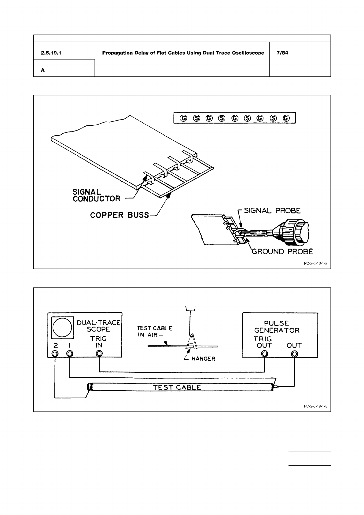
Figure 3 Cable Preparation and Cable Connection
Figure 4 Test Cable Hookup
IPC-TM-650
Number
Subject Date
Revision
Page 3 of 4
2.5.19.1
Propagation
Delay
of
Flat
Cables
Using
Dual
Trace
Oscilloscope
7/84
A
IPC-2-5-19-1-3
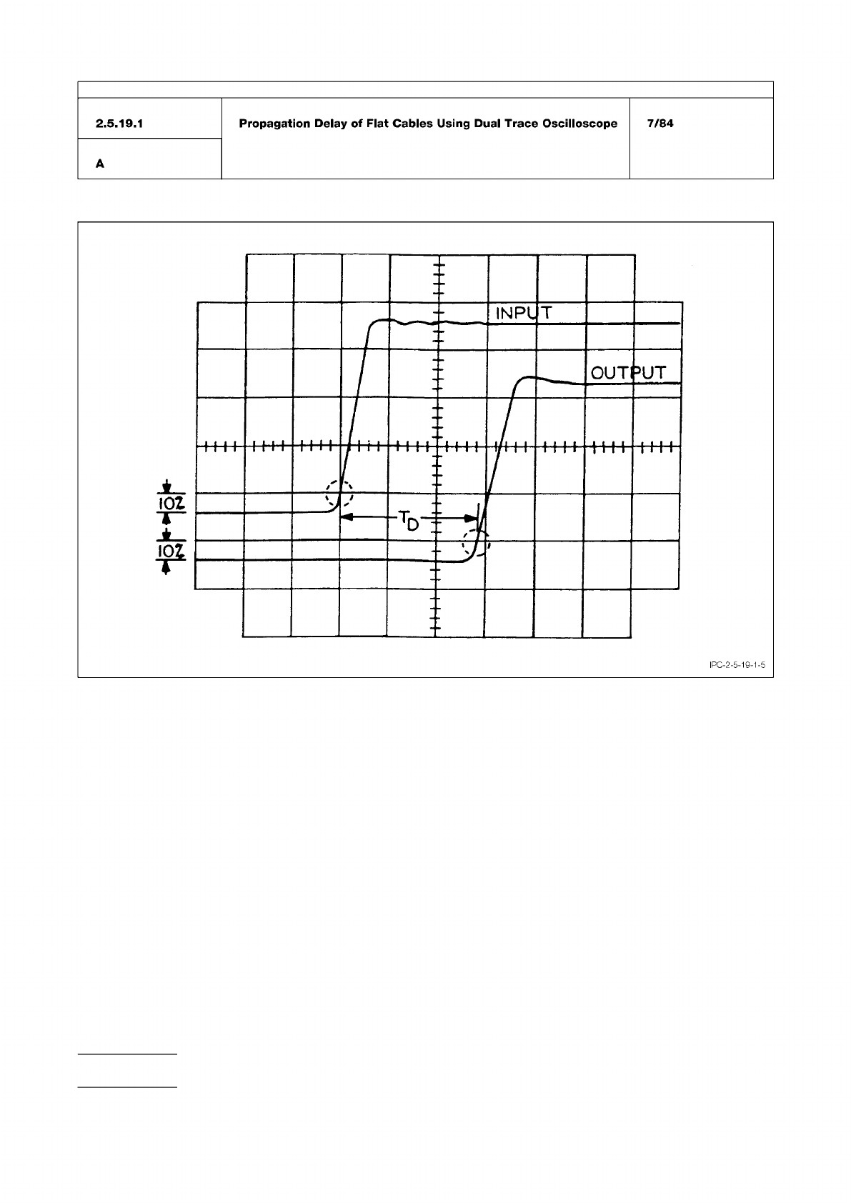
Figure 5 Dual Trace Oscilloscope Display
IPC-TM-650
Number
Subject Date
Revision
Page 4 of 4
7/84
Propagation
Delay
of
Flat
Cables
Using
Dual
Trace
Oscilloscope
IPC-2-5-19-1-5
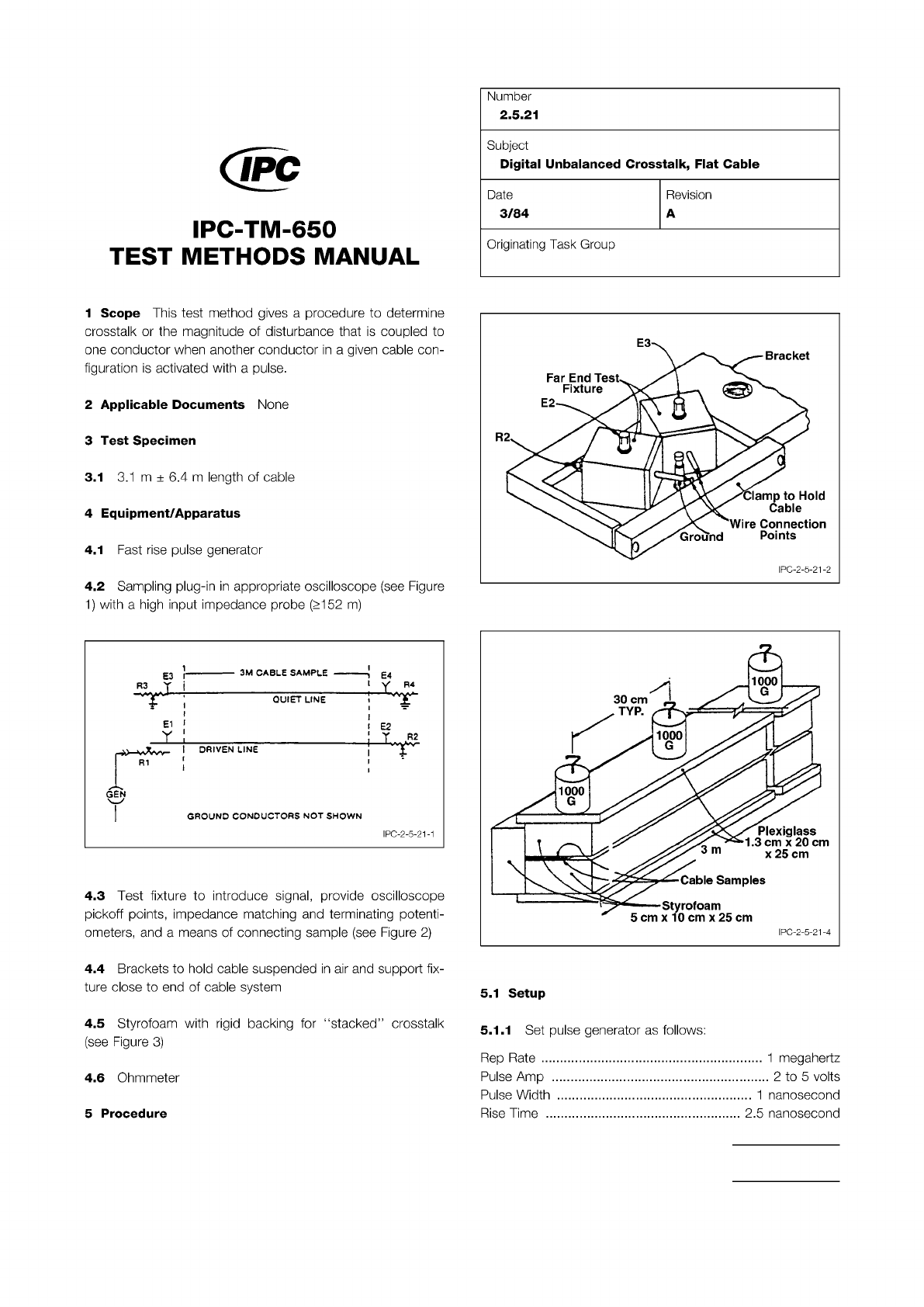
Figure 1 Oscilloscope
Figure 2 Connecting Sample
Figure 3 Crosstalk
The Institute for Interconnecting and Packaging Electronic Circuits
2215 Sanders Road • Northbrook, IL 60062
Material in this Test Methods Manual was voluntarily established by Technical Committees of the IPC. This material is advisory only
and its use or adaptation is entirely voluntary. IPC disclaims all liability of any kind as to the use, application, or adaptation of this
material. Users are also wholly responsible for protecting themselves against all claims or liabilities for patent infringement.
Equipment referenced is for the convenience of the user and does not imply endorsement by the IPC.
Page 1 of 2
回
IPC-TM-650
TEST
METHODS
MANUAL
1
Scope
This
test
method
gives
a
procedure
to
determine
crosstalk
or
the
magnitude
of
disturbance
that
is
coupled
to
one
conductor
when
another
conductor
in
a
given
cable
con¬
figuration
is
activated
with
a
pulse.
2
Applicable
Documents
None
3
Test
Specimen
3.1
3.1
m
±
6.4
m
length
of
cable
4
Equipment/Apparatus
4.1
Fast
rise
pulse
generator
4.2
Sampling
plug-in
in
appropriate
oscilloscope
(see
Figure
1)
with
a
high
input
impedance
probe
Q152
m)
GROUND
CONDUCTORS
NOT
SHOWN
I
PC-2-5-21-1
4.3
Test
fixture
to
introduce
signal,
provide
oscilloscope
pickoff
points,
impedance
matching
and
terminating
potenti¬
ometers,
and
a
means
of
connecting
sample
(see
Figure
2)
4.4
Brackets
to
hold
cable
suspended
in
air
and
support
fix¬
ture
close
to
end
of
cable
system
4.5
Styrofoam
with
rigid
backing
for
"stacked”
crosstalk
(see
Figure
3)
4.6
Ohmmeter
5
Procedure
Number
2.5.21
Subject
Digital
Unbalanced
Crosstalk,
Flat
Cable
Date
3/84
Revision
A
Originating
Task
Group
5.1
Setup
5.1.1
Set
pulse
generator
as
follows:
.....
1
megahertz
2
to
5
volts
..
1
nanosecond
2.5
nanosecond
Rep
Rate
...
Pulse
Amp
Pulse
Width
Rise
Time
..