IPC-TM-650 EN 2022 试验方法--.pdf - 第627页
T est Procedure Pass/Fail Criteria V alue Recorded Status Ground Measurements (2.5.33.1) 5 [ Pass [ Fail Tr ansient M easurements/Pass 1 (2.5.33.2) 2 V p eak V [ Pass [ Fail Tr ansient M easurements/Pass 2 (2.5.33.2) 2 V…
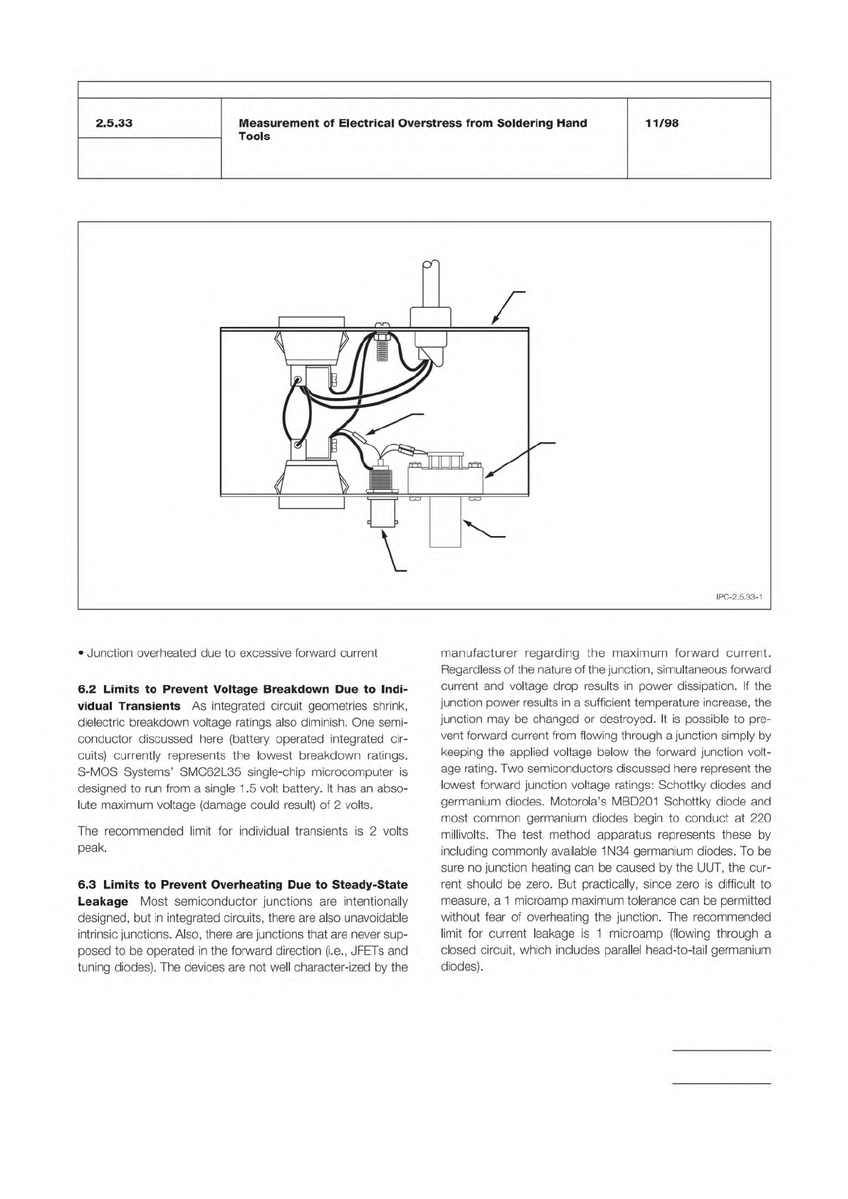
Figure 1 Current Leakage Test Circuit Configuration
AC RECEPTACLE
FOR VOLTMETER
AC RECEPTACLE
FOR UUT
BNC CONNECTOR
FOR VOLTMETER
TEST ELECTRODE
CARD EDGE
CONNECTOR
1K RESISTOR
METAL BOX
DIODES
G
R
N
B
L
K
W
H
T
TO AC
IPC-TM-650
Number
Subject Date
Revision
Page 3 of 5
IPC-2.5.33-1
2.5.33
Measurement
of
Electrical
Overstress
from
Soldering
Hand
Tools
11/98
•
Junction
overheated
due
to
excessive
forward
current
6.2
Limits
to
Prevent
Voltage
Breakdown
Due
to
Indi¬
vidual
Transients
As
integrated
circuit
geometries
shrink,
dielectric
breakdown
voltage
ratings
also
diminish.
One
semi¬
conductor
discussed
here
(battery
operated
integrated
cir¬
cuits)
currently
represents
the
lowest
breakdown
ratings.
S-MOS
Systems'
SMC62L35
single-chip
microcomputer
is
designed
to
run
from
a
single
1.5
volt
battery.
It
has
an
abso¬
lute
maximum
voltage
(damage
could
result)
of
2
volts.
The
recommended
limit
for
individual
transients
is
2
volts
peak.
6.3
Limits
to
Prevent
Overheating
Due
to
Steady-State
Leakage
Most
semiconductor
junctions
are
intentionally
designed,
but
in
integrated
circuits,
there
are
also
unavoidable
intrinsic
junctions.
Also,
there
are
junctions
that
are
never
sup¬
posed
to
be
operated
in
the
forward
direction
(i.e.,
JFETs
and
tuning
diodes).
The
devices
are
not
well
character-ized
by
the
manufacturer
regarding
the
maximum
forward
current.
Regardless
of
the
nature
of
the
junction,
simultaneous
forward
current
and
voltage
drop
results
in
power
dissipation.
If
the
junction
power
results
in
a
sufficient
temperature
increase,
the
junction
may
be
changed
or
destroyed.
It
is
possible
to
pre¬
vent
forward
current
from
flowing
through
a
junction
simply
by
keeping
the
applied
voltage
below
the
forward
junction
volt¬
age
rating.
Two
semiconductors
discussed
here
represent
the
lowest
forward
junction
voltage
ratings:
Schottky
diodes
and
germanium
diodes.
Motorola's
MBD201
Schottky
diode
and
most
common
germanium
diodes
begin
to
conduct
at
220
millivolts.
The
test
method
apparatus
represents
these
by
including
commonly
available
1
N34
germanium
diodes.
To
be
sure
no
junction
heating
can
be
caused
by
the
UUT,
the
cur¬
rent
should
be
zero.
But
practically,
since
zero
is
difficult
to
measure,
a
1
microamp
maximum
tolerance
can
be
permitted
without
fear
of
overheating
the
junction.
The
recommended
limit
for
current
leakage
is
1
microamp
(flowing
through
a
closed
circuit,
which
includes
parallel
head-to-tail
germanium
diodes).
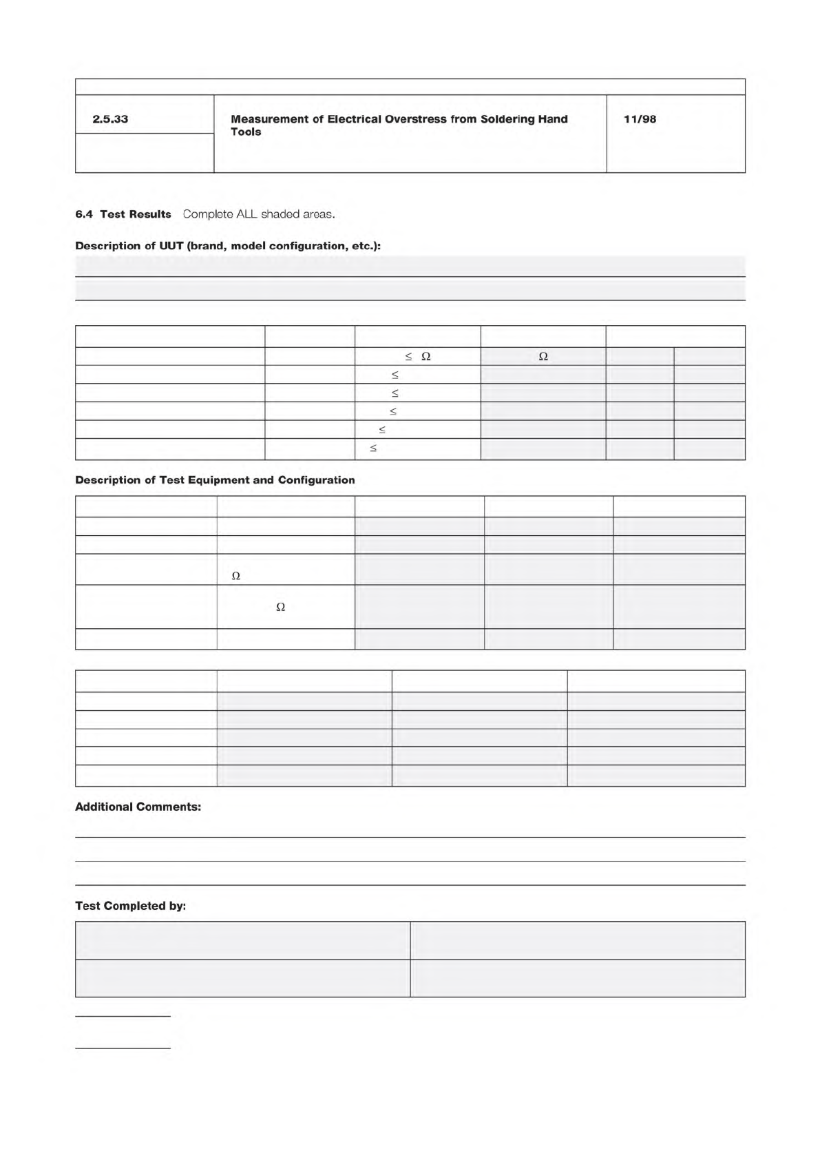
Test Procedure Pass/Fail Criteria Value Recorded Status
Ground Measurements (2.5.33.1) 5 [ Pass [ Fail
Transient Measurements/Pass 1 (2.5.33.2)
2 V peak V [ Pass [ Fail
Transient Measurements/Pass 2 (2.5.33.2)
2 V peak V [ Pass [ Fail
Transient Measurements/Pass 3 (2.5.33.2)
2 V peak V [ Pass [ Fail
Current Leakage Measurements (2.5.33.3)
1.0 µ-amp DC µ-amp DC [ Pass [ Fail
Current Leakage Measurements (2.5.33.3) 1.0 µ-amp ACrms µ-amp ACrms [ Pass [ Fail
Equipment Function Brand Model Calibration Date
AC millivoltmeter true mvAC/rms
DC millivoltmeter 60 mv DC
Ohmmeter resistances beyond 5
M
Storage Oscilloscope 100 Mhz bandwidth or
faster, 1 M
input
vertical amplifier
Constant Current Source 10 milliamps DC
Equipment Scale Used Cal / Std Meas. Baseline Meas.
AC millivoltmeter
DC millivoltmeter
Ohmmeter
Storage Oscilloscope
Constant Current Source
NAME: DATE:
COMPANY: PHONE:
IPC-TM-650
Number
Subject Date
Revision
Page 4 of 5
2.5.33
Measurement
of
Electrical
Overstress
from
Soldering
Hand
Tools
11/98
6.4
Test
Results
Complete
ALL
shaded
areas.
Description
of
UUT
(brand,
model
configuration,
etc.):
Q Q
Description
of
Test
Equipment
and
Configuration
Q
Q
Additional
Comments:
Test
Completed
by:
3.1 Coupon Design Rules
Certain designs rules must be
applied to achieve thermal uniformity. Electronic design files
for coupon construction are available from the equipment
supplier or printed board supplier. The resistance values (volt-
age drops) for each coupon are monitored independently for
each electrical net in test, using a four wire measurement
technique.
The test coupon(s) is incorporated on the panel to monitor or
qualify design, materials, or processes of product and/or reli-
ability assurance.
4 Apparatus or Material
At the time of publication of this
test method, 4.1 and 4.2 list the only known equipment
manufacturers of this test equipment. Equivalent test systems
may be used that operate on principles similar to those iden-
tified in Method A or B. IPC encourages their submission
along with relevant validation test data. This test method will
be revised as necessary to include these test systems as this
information becomes available.
Validation of this test method was performed with the equip-
ment listed in 4.1 and 4.2. Test conditions for the validation
are provided in 6.5. If alternate test equipment is used, valida-
tion in accordance with IPC-MDP-650 and 6.5 is recom-
mended.
4.1 Method A
4.1.1
This equipment is available from:
PWB Interconnect Solutions Inc. (Canada)
URL: www.pwbcorp.com
Equipment Type: IST
4.1.2
Two (2) four-pin, 2.54 mm [0.1 in] male connector
(ITW Pancon MFSS100-4-D or equivalent).
4.1.3
Sn60Pb40, Sn63Pb37, or lead free solder.
4.1.4
Solder flux.
4.1.5
Soldering iron.
4.2 Method B
4.2.1
This equipment is available from:
i3 Electronics (USA)
(formerly Endicott Interconnect Technologies)
URL: www.i3electronics.com
Equipment Type: CITC, CITC-TCR
4.2.2
4-wire multimeter, capable of measuring milliohms
4.2.3
Thermal imaging equipment – optional
5 Procedures
5.1 Sample Selection
5.1.1
Bench top measure the resistance of each net of the
coupon with a 4-wire multimeter. A net with an open cannot
be tested. A net with a short must be reworked to test the
coupon.
5.1.2 Coupon Selection
Select coupons for evaluation
based upon the test required as described in 5.1.2.1 through
5.1.2.3.
5.1.2.1 Random Sampling
A sample chosen without
regard to any characteristic of the individual coupons within a
population, within one or more lots.
5.1.2.2 Selective Sampling
A sample chosen based on
the resistance measurements of the sense and power nets.
Testing may include high, midrange and low resistance mea-
surements.
5.1.2.3 Comparative Sampling
A sample chosen based
on the resistance measurements of the sense and power
nets. Testing should include similar resistance measurements
for the populations being tested.
5.2 Method A Procedure
5.2.1 Single Sense Testing
Solder two four-pin male con-
nectors in the 1.02 mm [0.040 in] holes at the left and right
edges of the coupon (see Figure 3-1). A solder fillet must be
apparent on both sides of the coupon.
5.2.1.1 Dual Sense Testing (Optional)
When Dual Sense
Testing is required, solder three four-pin male connectors in
the 1.02 mm [0.040 in] holes at the edges of the coupon (see
Figure 5-1). A solder fillet must be apparent on both sides of
the coupon.
Dual Sense coupons may be tested using the Single
Sense Testing method.
Number
2.6.26
Subject
DC Current Induced Thermal Cycling Test
Date
5/14
Revision
A
IPC-TM-650
NOTE:
Page
3
of
10