IPC-TM-650 EN 2022 试验方法--.pdf - 第631页
5.2.7.1 Ambient Resistance The auto ranging multimeter measures the ambient resistance (voltage drop ) of the net t hat heats the coupon with DC current . 5. 2. 7.2 R es ist anc e at Test Tem per atu re The s yst em soft…
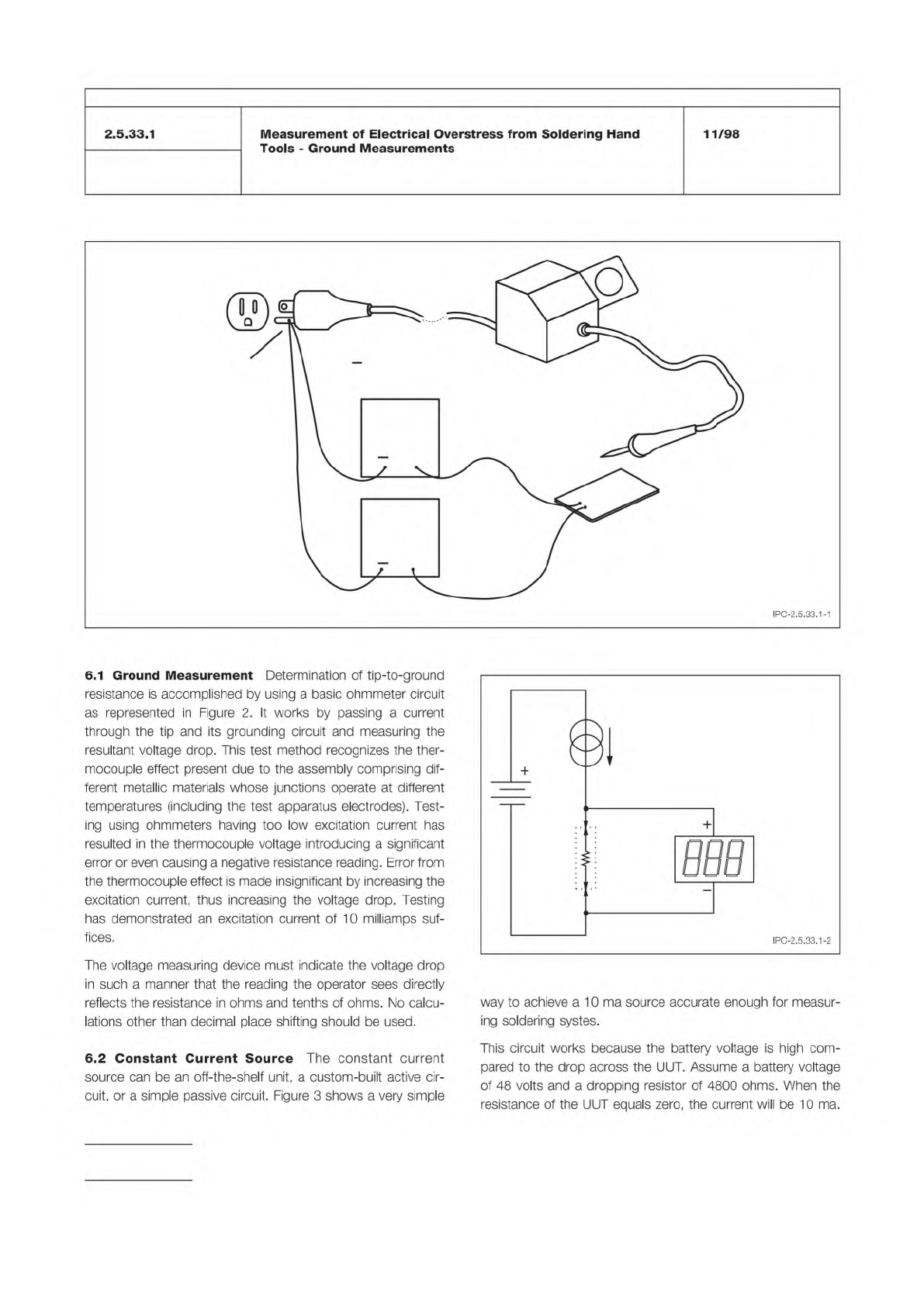
Figure 1 Test Apparatus
10 MA.
CURRENT
SOURCE
GROUND
REFERENCE
POINT
MILLI-
VOL
T
METER
+
+
+
ELECTRODE
( )
UNIT UNDER
TEST (UUT)
TEST
ELECTRODE ( )
Figure 2 Block Diagram of Test Apparatus
UUT
10 MA
CURRENT
REGULATOR
MILLIVOLT
METER
IPC-TM-650
Number
Subject Date
Revision
Page 2 of 3
2.5.33.1
Measurement
of
Electrical
Overstress
from
Soldering
Hand
Tools
-
Ground
Measurements
11/98
IPC-2.5.33.1-1
6.1
Ground
Measurement
Determination
of
tip-to-ground
resistance
is
accomplished
by
using
a
basic
ohmmeter
circuit
as
represented
in
Figure
2.
It
works
by
passing
a
current
through
the
tip
and
its
grounding
circuit
and
measuring
the
resultant
voltage
drop.
This
test
method
recognizes
the
ther¬
mocouple
effect
present
due
to
the
assembly
comprising
dif¬
ferent
metallic
materials
whose
junctions
operate
at
different
temperatures
(including
the
test
apparatus
electrodes).
Test¬
ing
using
ohmmeters
having
too
low
excitation
current
has
resulted
in
the
thermocouple
voltage
introducing
a
significant
error
or
even
causing
a
negative
resistance
reading.
Error
from
the
thermocouple
effect
is
made
insignificant
by
increasing
the
excitation
current,
thus
increasing
the
voltage
drop.
Testing
has
demonstrated
an
excitation
current
of
10
milliamps
suf¬
fices.
The
voltage
measuring
device
must
indicate
the
voltage
drop
in
such
a
manner
that
the
reading
the
operator
sees
directly
reflects
the
resistance
in
ohms
and
tenths
of
ohms.
No
calcu¬
lations
other
than
decimal
place
shifting
should
be
used.
6.2
Constant
Current
Source
The
constant
current
source
can
be
an
off-the-shelf
unit,
a
custom-built
active
cir¬
cuit,
or
a
simple
passive
circuit.
Figure
3
shows
a
very
simple
way
to
achieve
a
10
ma
source
accurate
enough
for
measur¬
ing
soldering
systes.
This
circuit
works
because
the
battery
voltage
is
high
com¬
pared
to
the
drop
across
the
UUT.
Assume
a
battery
voltage
of
48
volts
and
a
dropping
resistor
of
4800
ohms.
When
the
resistance
of
the
UUT
equals
zero,
the
current
will
be
10
ma.

5.2.7.1 Ambient Resistance
The auto ranging multimeter
measures the ambient resistance (voltage drop) of the net that
heats the coupon with DC current.
5.2.7.2 Resistance at Test Temperature
The system
software calculates and displays the resistance at the test
temperature. The available stress testing range is from 50 -
270 °C [122 - 518 °F]. The equation used to calculate the tar-
get resistance is as follows:
Target Resistance = Rrm x (1 + αT [Th - Trm])
where:
αT = Estimated thermal coefficient of resistance for the inter-
connect
Rrm = Resistance of coupon at ambient temperature
Th = Test temperature
Trm = Ambient Temperature (approximately 25 °C [77 °F])
5.2.7.3 Failure Threshold
The system software calculates
and displays the resistance change. This is adjustable from a
1% to a 100% increase. The typical failure threshold value is a
10% change in resistance. The equation to calculate the fail-
ure threshold is as follows:
Failure Threshold = (RT1 x Rr) + RT1
where:
Failure Threshold is in resistance
RT1 = Resistance of coupon at test temperature for Cycle 1
Rr = Resistance change (typically 10%)
5.2.7.4 Current
The system selects an initial current based
on the ambient resistance of the coupon and the current
table. The current tables are derived from software libraries on
the Method A test equipment. During the pre-cycling
sequence, the initial current is adjusted for each coupon to
assure the test temperature resistance is achieved in three
minutes ± precycle time window (see 5.2.7.5).
Additional equations/algorithms used by Method A
that establish the initial current selection for pre-cycling, rela-
tive to the relationship of coupon interconnect resistance αT,
coupon construction and stress test temperature to be
achieved are considered proprietary at this time.
5.2.7.5 Pre-Cycling
Pre-cycling is initiated by the applica-
tion of the selected current to the coupon; the computer
monitors the coupon’s performance throughout a 30 second
and 60 second cycle. The resistance level is monitored and
the current is adjusted based on the resistance reading.
These short duration tests adjust the current to prevent the
coupon heating rate being too fast on the first pre-cycle. The
computer monitors and records the coupon’s performance on
the first pre-cycle. If at the end of the first pre-cycle, the cou-
pon achieves the specified resistance level in three minutes ±
precycle time window, it will be accepted for subsequent
stress testing. If the resistance value was not achieved in this
time frame, the coupon will automatically be pre-cycled again
with a revised or compensated current. The system will retest
using revised conditions until all coupons are accepted or
rejected for stress testing.
The equation(s)/algorithms used by Method A to com-
pensate the DC current are considered proprietary at the time
of publication of this method revision.
5.2.7.6
Forced air cooling is commenced after each pre-
cycle to cool the coupons to ambient temperature.
5.2.7.7
The system automatically records and saves all
information regarding the pre-cycling conditions for subse-
quent stress testing.
5.2.8 Stress Cycle Test Sequence
The following para-
graphs detail the sequence for a single coupon; however this
sequence is done at all test heads simultaneously.
5.2.8.1
When the pre-cycle sequence is complete, the
Method A stress test is initiated by applying the same DC cur-
rent level established for each individual coupon during the
pre-cycle operation for three minutes. The computer monitors
and records the relative changes in resistance of the plated
barrel and internal connections throughout the heating cycle.
5.2.8.2
The three minutes of heating is followed by forced
air cooling. Cooling time is a function of overall thickness and
construction of the coupon. The computer monitors and
records the coupon’s performance throughout the cooling
cycle.
5.2.8.3
The individual coupons are placed on the tester and
are continually thermal cycled using their customized heating
and cooling conditions until the rejection criteria is achieved or
the maximum number of cycles is completed.
5.2.8.4
The coupon’s resistance ‘‘delta’’ (the variance from
resistance of coupon at test temperature for Cycle 2)
increases (positively) as failure inception occurs. The rate of
change in the delta is indicative of the mechanical change
(failure) within the barrel and/or internal connections.
Number
2.6.26
Subject
DC Current Induced Thermal Cycling Test
Date
5/14
Revision
A
IPC-TM-650
NOTE:
NOTE:
Page
5
of
10
ANSI/J-STD-001
IPC-TM-650
The Institute for Interconnecting and Packaging Electronic Circuits
2215 Sanders Road • Northbrook, IL 60062
Material in this Test Methods Manual was voluntarily established by Technical Committees of the IPC. This material is advisory only
and its use or adaptation is entirely voluntary. IPC disclaims all liability of any kind as to the use, application, or adaptation of this
material. Users are also wholly responsible for protecting themselves against all claims or liabilities for patent infringement.
Equipment referenced is for the convenience of the user and does not imply endorsement by the IPC.
Page 1 of 4
Number
IPC-TM-650
TEST
METHODS
MANUAL
Subject
Measurement
of
Electrical
Overstress
from
Soldering
Hand
Tools
-
Transient
Measurements
Originating
Task
Group
Manual
Soldering
Task
Group
(5-22c)
Date
11/98
Revision
1
Scope
This
test
method
deals
only
with
transients
gener¬
ated
within
the
Unit
Under
Test
(UUT)
and
not
with
transients
originating
elsewhere
(i.e.,
power
line
transients),
which
propa¬
gate
through
the
UUT.
This
procedure
measures
transient
voltage
events
appearing
at
the
hot
tip
of
an
electric
hand
soldering/desoldering
tool,
which
could
be
seen
by
the
workpiece.
The
test
electrode
and
measuring
equipment
represent
a
workpiece
having
a
high
impedance.
There
are
two
times
when
transients
testing
should
be
done:
•
Equipment
qualification
for
purchase
•
Incoming
inspection
of
new
or
repaired
equipment
A
storage
oscilloscope
is
used
to
observe
and
measure
tran¬
sient
events.
The
test
electrode
is
coupled
to
the
vertical
input
of
the
oscilloscope
via
a
1
0
MQ
probe.
The
UUT
may
be
iso¬
lated
from
ambient
electronic
noise
by
placing
it
in
a
screen
room
or
shielded
enclosure
and
supplying
filtered
AC
power.
Inside
the
shield,
the
hot
tip
of
the
UUT
is
touched
to
the
test
electrode.
This
test
may
be
falsely
influenced
by
radio
frequency
interfer¬
ence
and
electromagnetic
interference
from
lighting
and
equipment
found
in
the
workplace
and
testing
area.
This
will
normally
be
demonstrated
by
ambient
transients
of
1
.5
V
peak
being
present.
At
a
minimum,
shielded
test
leads
should
be
utilized.
To
avoid
these
influences
it
may
be
necessary
to
per¬
form
the
leakage
and
transient
tests
in
a
screen
room.
In
lieu
of
a
screen
room
a
separate
test
procedure,
see
Method
2.5.33.4,
which
makes
a
low
cost
shielded
enclosure,
which
should
provide
adequate
shielding
for
the
performance
of
these
test
procedures.
Warning:
This
is
a
laboratory
test
procedure
that
may
of
necessity
expose
terminals
that
carry
line
voltages.
All
stan¬
dard
laboratory
safety
procedures
regarding
the
setup
and
performance
of
tests
with
line
voltage
equipment
must
be
observed
at
all
times.
Caution:
This
test
is
performed
with
soldering
systems
at
their
normal
operating
temperature.
Test
personnel
must
take
adequate
precautionary
steps
to
protect
themselves
and
oth¬
ers
from
potential
burns.
2
Applicable
Documents
Requirements
for
Soldered
Electrical
and
Electronic
Assemblies
Test
Methods
Manual
2.5.33
Measurement
of
Electrical
Overstress
from
Solder¬
ing
Hand
Tools
2.5.33.4
Measurement
of
Electrical
Overstress
from
Solder¬
ing
Hand
Tools
-
Shielded
Enclosure
3
Test
Specimens
Test
specimens
for
this
procedure
are
detailed
in
Method
2.5.33.
4
Equipment/Apparatus
Apparatuses
utilized
by
the
pro¬
cedures
that
make
up
this
test
method
are
given
in
4.1
through
4.5.2.
4.1
Test
electrode
(see
Section
3)
4.2
Storage
oscilloscope,
100
Mhz
bandwidth
or
faster,
1
MQ
input
vertical
amplifier
4.3
Power
line
filter,
20
ampere
@115
VAC,
50
dB
insertion
loss
@
5
Mhz/50Q
4.4
Oscilloscope
probe
-
X10
Attenuation
4.5
Optional
4.5.1
Screen
camera,
diskette,
or
hard
copy
waveform
printer
4.5.2
Screen
room
or
shielded
enclosure
capable
of
accom¬
modating
the
entire
UUT,
cord,
and
handpiece.
A
filtered
AC
power
receptacle
shall
be
available
from
within
(see
Method
2.5.33.4).
4.6
Preparation
of
Apparatus
Turn
on
the
oscilloscope
and
allow
it
to
warm
up.
Connect
the
UUT
to
a
shielded
AC
line
filter
assembly
as
shown
in
Figure
1
and
configure
for
typical
operation.
Note:
The
plugs
are
in
power
receptacles
during
measure¬
ments.
They
are
shown
unplugged
in
Figure
1
for
clarity.