IPC-TM-650 EN 2022 试验方法--.pdf - 第650页
T a ble I T est Duration Condition Length of T est (Days) Figure 1 Graphical Representatio n of Moisture-Resistance T est IPC-TM-650 Page 2 of 3 IPC-3-5-1 . 80-98% 70 65 60 55 50 45 40 35 25 10 5 0 -5 -10 STEP 7b STEP 7 …
Steady State Test
Humidity—Temperature Cycling Test
Material in this Test Methods Manual was voluntarily established by Technical Committees of the IPC. This material is advisory only
and its use or adaptation is entirely voluntary. IPC disclaims all liability of any kind as to the use, application, or adaptation of this
material. Users are also wholly responsible for protecting themselves against all claims or liabilities for patent infringement.
Equipment referenced is for the convenience of the user and does not imply endorsement by the IPC.
Page 1 of 3
r
ASSOCIATION
CONNECTING
/
ELECTRONICS
INDUSTRIES
2215
Sanders
Road
Northbrook,
IL
60062-6135
IPC-TM-650
TEST
METHODS
MANUAL
Number
3.5
Subject
Humidity,
Connectors
Date
Revision
7/75
A
Originating
Task
Group
N/A
1
.0
Scope
1.1
To
determine
the
effect
on
the
connector
of
prolonged
exposure
to
conditions
of
high
humidity
at
various
tempera¬
tures.
Two
conditions
of
test
are
provided
as
follows:
Used
to
evaluate
the
hydroscopic
nature
of
insulating
materials
as
evidenced
by
deteriorated
physical
properties
(dimensions,
mechanical
strength,
etc.)
or
degraded
electrical
properties
(e.g.,
insulation
resistance).
Used
to
evaluate
the
effectiveness
of
seals
and
gaskets
in
the
presence
of
a
pres¬
sure
differential
induced
by
varying
temperatures;
the
corro¬
sion
resistance
of
metals
and
finishes
exposed
to
alternate
periods
of
condensation
and
drying;
and
the
hydroscopic
nature
of
insulating
materials,
with
any
degradation
acceler¬
ated
by
the
“breathing”
action
imposed
by
varying
tempera¬
tures.
Optional
exposures
to
sub-freezing
temperatures
and
to
mechanical
vibration
exaggerate
any
structural
deterioration
of
insulating
materials.
2
.0
Reference
Documents
2.1
Information
in
this
section
is
intended
to
parallel
the
test
method
described
in
EIA-RS-364/TP-31
.
3
.0
Test
Specimen
3.1
A
connector
(plug
and
receptacle)
complete
with
appli¬
cable
guide,
keying,
and
engaging
hardware
or
a
card-
edge
receptacle
and
mating
printed
circuit
board
(if
required
by
the
individual
connector
specification).
The
connector
or
recep¬
tacle
shall
be
mated
or
unmated
as
specified
in
the
individual
connector
specification.
3.2
Neither
the
plug
nor
the
receptacle
shall
be
mounted
or
terminated
during
the
test,
unless
such
mounting
(or
termina¬
tion)
is
necessary
(1)
to
insure
the
mechanical
integrity
of
the
component,
(2)
to
measure
the
specified
electrical
character¬
istics),
(3)
was
a
requirement
of
previously
imposed
environ¬
mental
or
functional
tests.
3.3
Printed
circuit
boards
may
be
conformal
coated
to
reduce
the
effect
of
their
deterioration
due
to
moisture
on
the
connector
characteristic(s)
under
evaluation.
The
coating
shall
not
be
applied
to
any
portion
of
the
connector
under
test.
3.4
The
plug,
receptacle
or
mated
connector
shall
be
sus¬
pended
or
supported
within
the
test
chamber
in
a
normal
(or
typical
mounting
attitude
using
non-corrosive
material
(e.g.,
plastic,
corrosion
resisting
steel,
etc.)).
The
technique
utilized
shall
not
impede
the
flow
of
circulating
air
over
and
around
the
test
specimen.
4
.0
Apparatus
4.1
A
temperature-humidity
chamber
capable
of
maintaining
dry
bulb
temperatures
from
+
25℃
to
+
65℃
within
土
2
℃
of
the
set
temperatures
and
relative
humidity
greater
than
90%
during
ascending
or
constant
temperature
operation
and
greater
than
80%
during
descending
temperature
operation.
Circulation
of
air
within
the
chamber
shall
be
at
a
minimum
cubic
rate
equivalent
to
five
times
of
non-corrosive
material
and
shall
prevent
the
dripping
of
condensate
onto
the
test
specimen.
4.2
A
temperature
chamber,
when
required,
capable
of
maintaining
a
temperature
of
-10℃
+0,
-4℃.
4.3
A
temperature
measuring
device,
when
required,
of
suit¬
able
range
for
the
specified
test
condition.
4.4
A
vibration
system,
when
required,
capable
of
producing
approximately
simple
harmonic
motion
at
a
double
amplitude
of
0.60
inch
in
the
frequency
range
from
1
0
to
55
Hz.
5
.0
Procedure
5.1
Pre-Conditioning
The
test
specimen
shall
be
condi¬
tioned
in
a
dry
oven
at
a
temperature
of
50℃
±5℃
for
a
mini¬
mum
period
of
twenty-four
hours.
After
stabilization
at
room
ambient
conditions,
the
test
specimen
shall
be
subjected
to
the
pre-test
measurements
specified
in
the
individual
connec¬
tor
specification.
5.2
Steady-State
Test
5.2.1
The
test
specimen
shall
be
suspended
within
the
humidity
chamber
and
subjected
to
a
relative
humidity
of
90-95%
at
a
temperature
of
40℃
土
2
℃
for
a
period
of
time
corresponding
to
one
of
the
test
conditions
shown
in
Table
1
.
Unless
otherwise
specified,
Test
Condition
D
shall
apply.
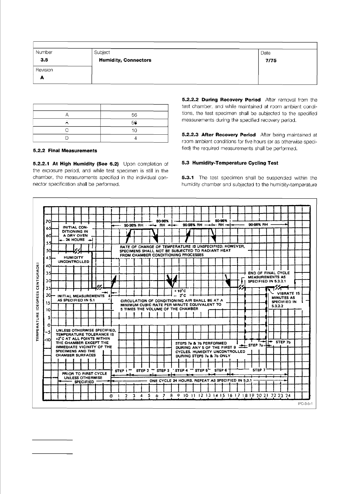
Table I Test Duration
Condition Length of Test (Days)
Figure 1 Graphical Representation of Moisture-Resistance Test
IPC-TM-650
Page 2 of 3
IPC-3-5-1
.
80-98%
70
65
60
55
50
45
40
35
25
10
5
0
-5
-10
STEP
7b
STEP
7
ONE
CYCLE
24
HOURS.
REPEAT
AS
SPECIFIED
IN
5.3.1
ED
SPECIF
0
PRIOR
TO
FIRST
CYCLE
UNLESS
OTHERWISE
INITIAL
CON-
.
DITIONING
IN
A
DAY
OVEN
-
一
24
HOURS
7
END
OF
FINAL
CYCLE
MEASUREMENTS
AS
SPECIFIED
IN
5.3.3.1
rate
of
change
of
temperature
is
unspecified;
however,
SPECIMENS
SHALL
NOT
BE
SUBJECTED
TO
RADIANT
HEAT
FROM
CHAMBER
CONDITIONING
PROCESSES
STEPS
7a
&
7b
PERFORMED
DURING
ANY
5
OF
THE
FIRST
9
CYCLES.
HUMIDITY
UNCONTROLLED
DURING
STEPS
7a
&
7b
ONLY
3
HUMIDITY
UNCONTROLLED
UNLESS
OTHERWISE
SPECIFIED,
TEMPERATURE
TOLERANCE
IS
±2°C
AT
ALL
POINTS
WITHIN
THE
CHAMBER
EXCEPT
THE
IMMEDIATE
VICINITY
OF
THE
SPECIMENS
AND
THE
CHAMBER
SURFACES
5
6
7
8
9
iO
11
12
13
14
15
16
I
7
1
8
19
20
21
?2
23
24
1
l
i
一
・
l
।
•
l
I
一八
A
匕
i
VIBRATE
15
_
MINUTES
AS
SPECIFIED
IN
—
532.2
20-
INITIAL
measurements
…
AS
SPECIFIED
IN
5.1
」
+
10℃
-
20c
CIRCULATION
OF
CONDITIONING
AIR
SHALL
BE
AT
A
MINIMUM
CUBIC
RATE
PER
MINUTE
EQUIVALENT
TO
5
TIMES
THE
VOLUME
OF
THE
CHAMBER
A
56
B
21
C
10
D
4
5.2.2
Final
Measurements
5.2.2.
1
At
High
Humidity
(See
6.2)
Upon
completion
of
the
exposure
period,
and
while
test
specimen
is
still
in
the
chamber,
the
measurements
specified
in
the
individual
con¬
nector
specification
shall
be
performed.
5.2.2.2
During
Recovery
Period
After
removal
from
the
test
chamber,
and
while
maintained
at
room
ambient
condi¬
tions,
the
test
specimen
shall
be
subjected
to
the
specified
measurements
during
the
specified
recovery
period.
S.2.2.3
After
Recovery
Period
After
being
maintained
at
room
ambient
conditions
for
five
hours
(or
as
otherwise
speci¬
fied)
the
required
measurements
shall
be
performed.
5.3
Humidity-Temperature
Cycling
Test
5.3.1
The
test
specimen
shall
be
suspended
within
the
humidity
chamber
and
subjected
to
the
humidity-temperature
Number
3.5
Subject
Humidity,
Connectors
Date
7/75
Revision
A
A
56
B
21
C
10
D
4
IPC-TM-650
Page 3 of 3
Number
2.6.1.
1
Subject
Fungus
Resistance
-
Conformal
Coating
Date
07/00
Revision
fine
mist
from
a
previously
sterilized
atomizer
or
nebulizer.
In
spraying
the
test
and
control
items,
care
should
be
taken
to
spray
all
surfaces
which
are
exposed
during
use
or
mainte¬
nance.
If
the
surfaces
are
nonwetting,
spray
until
initiation
of
droplet
coalescence.
Incubation
is
to
be
started
immediately
following
the
inoculation.
5.5
Test
Incubation
of
Test
Items
5.5.1
Incubate
test
items
under
static
temperature
of
28-30℃
[82.4-86°F]
with
a
minimum
85%
relative
humidity.
5.5.2
After
seven
days,
inspect
the
growth
on
the
control
items
to
be
assured
that
the
environmental
conditions
are
suitable
for
growth.
If
inspection
reveals
that
the
environmen¬
tal
conditions
are
unsuitable
for
growth,
the
entire
test
shall
be
repeated.
5.5.3
If
the
control
items
show
satisfactory
fungus
growth,
continue
the
test
for
a
period
of
28
days
from
the
time
of
inoculation,
or
as
specified.
5.6
Evaluation
5.6.1
Report
those
specimens
which
were
found
to
be
nutri¬
ent
to
fungus
growth.
5.6.2
Corrosion
should
be
noted
separately
from
the
fungus
test
results.
6.0
Notes
6.1
Source
for
Micro-organisms
6.1.1
American
Type
Culture
Collection
10801
University
Blvd.
Manassas,
VA
20110-2209
(USA)
703-365-2700
http://www.atcc.org
6.2
Secondary
Sources
for
Microorganisms
6.2.1
Pioneering
Research
Division
U.S.
Army
Natick
Laboratories
Natick,
Massachusetts
01
760
6.2.2
North
University
St.
Peoria,
IL
61604
Contact:
Dr.
Stephen
Peterson
309-685-401
1
6.3
After
evaluation,
the
materials
and
the
test
chamber
must
be
decontaminated
by
exposure
on
all
sides
to
ultravio¬
let
rays
(360
nm)
for
a
minimum
of
two
hours,
or
sprayed
with
a
solution
of
1:750
zephiran
chloride
solution.
(One
part
zephi-
ran
chloride
to
750
parts
distilled
water).
6.4
Safety
Observe
all
appropriate
precautions
on
MSDS
for
chemicals
involved
in
this
test
method.