IPC-TM-650 EN 2022 试验方法--.pdf - 第654页
Figure 4 T ol eran ces for T erminal-Peak Sawtooth Shock Pulse Figure 5 T ol eran ce Limits for Measuring System Frequency Respons e IPC-TM-650 Page 5 of 5 SYSTEM INCLUDING TRANSDUCER Number 3.8 Subject Mechanical Shock,…

specimen between layers of absorbent paper and roll three or
four times. Repeat until there is no apparent absorption by the
paper. Place immediately into the tared weighing bottle, cover
the bottle, weigh and record to the nearest 0.001 gram.
NOTE:
This is the most critical part of the test. Care must be
given to removing moisture from the specimens. Limit time
between removal from water to putting in weighing bottle to
≤30 seconds.
5.3 Evaluation
Calculate the water absorption for each
specimen as follows:
Percent of Absorption =
W
2
− W
1
W
1
x 100
where:
W
1
= weight before immersion (see 5.2.1)
W
2
= weight after immersion (see 5.2.3)
Average the results of the three specimens and report this
average to nearest 0.1%.
NOTE:
If the range of results for the three individual speci-
mens exceeds1%, the test must and
be repeated.
Number
2.6.2
Subject
Moisture Absorption, Flexible Printed Wiring
Date
2/12
Revision
D
IPC-TM-650
shall
Page
2
of
2
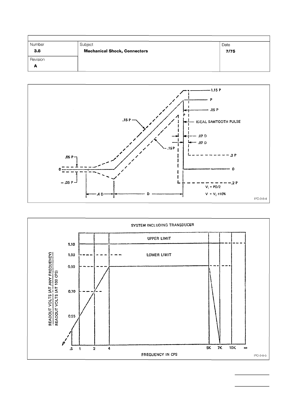
Figure 4 Tolerances for Terminal-Peak Sawtooth Shock Pulse
Figure 5 Tolerance Limits for Measuring System Frequency Response
IPC-TM-650
Page 5 of 5
SYSTEM
INCLUDING
TRANSDUCER
Number
3.8
Subject
Mechanical
Shock,
Connectors
Date
7/75
Revision
A
IPC-3-8-4
<sd
°
OOL
l
s
S11o>
InoovwH
FREQUENCY
IN
CPS
IPC-3-8-5
IPC-CC-830
Material in this Test Methods Manual was voluntarily established by Technical Committees of IPC. This material is advisory only
and its use or adaptation is entirely voluntary. IPC disclaims all liability of any kind as to the use, application, or adaptation of this
material. Users are also wholly responsible for protecting themselves against all claims or liabilities for patent infringement.
Equipment referenced is for the convenience of the user and does not imply endorsement by IPC.
Page 1 of 4
r
ASSOCIATION
CONNECTING
/
ELECTRONICS
INDUSTRIES
®
221
5
Sanders
Road
Northbrook,
IL
60062-6135
IPC-TM-650
TEST
METHODS
MANUAL
1
Scope
This
test
method
is
to
determine
the
degradation
of
insulating
materials
by
examination
of
the
visual
and
electri¬
cal
insulation
resistance
properties
of
printed
board
speci¬
mens
after
exposure
to
high
humidity
and
heat
conditions.
This
method
allows
testing
with
(Method
A)
or
without
(Method
B)
Conformal
Coating.
When
not
specified,
Method
A
is
the
default
method.
2
Applicable
Documents
Qualification
and
Performance,
Insulating
Com¬
pounds
for
Printed
Circuits
Assemblies
3
Test
Specimens
3.1
Test
specimens
shall
be
comprised
of
a
minimum
of
two
conductor
lines
per
conductive
layer,
sufficient
to
allow
resis¬
tance
testing
between
adjacent
conductor
patterns
both
between
layers
and
on
the
same
layer.
See
6.1
for
examples
of
test
specimen
patterns
recommended
for
this
test
method.
4
Apparatus
or
Material
4.1
A
clean
test
chamber
capable
of
programming
and
recording
an
environment
of
temperature
ranging
between
25
±
2
[77
°F
±
4
°F)
and
65
±
2
[149
°F
±
4
°F],
and
85%
to
93%
relative
humidity.
4.2
A
power
supply
capable
of
producing
a
standing
bias
potential
of
100
volts
DC
with
a
tolerance
of
±
10%.
4.3
A
resistance
meter
capable
of
reading
high
resistance
at
the
voltage
described
in
the
procurement
documentation.
4.4
Solder
or
Flux-Cored
Solder
Flux
shall
be
removable
in
a
manner
which
will
not
adversely
affect
the
test
specimen.
4.5
Soft
Bristle
Brush.
4.6
Deionized
or
distilled
water
(2
megohm-cm,
minimum
resistivity
recommended).
4.7
Isopropyl
alcohol.
Number
2.6.3
Subject
Moisture
and
Insulation
Resistance,
Printed
Boards
Date
05/04
Revision
F
Originating
Task
Group
Rigid
Printed
Board
Performance
Task
Group
(D-33a)
4.8
Drying
oven(s)
capable
of
maintaining
50
±
5
[122
°F
±
9
°F]
and
125
±
5
[257
°F
±
9
°F].
4.9
Insulating
compound
(conformal
coating)
which
con¬
forms
to
IPC-CC-830.
4.10
Equipment
necessary
to
apply
and
cure
conformal
coating.
5
Procedure
5.1
Specimen
Preparation
5.1.1
Mark
specimen
with
positive,
permanent,
and
non¬
contaminating
identification.
5.1.2
Visually
inspect
the
test
specimens
for
any
obvious
defects,
as
described
in
the
applicable
performance
specifica¬
tion.
If
any
test
specimen
is
noncompliant,
the
test
specimen
should
be
replaced
and
the
replacement
noted.
5
J
.3
Solder
single
stranded
(to
decrease
the
opportunity
for
flux
contamination
from
the
wire)
insulated
wire
which
is
not
affected
by
the
test
environment
to
each
of
the
connection
points
of
the
test
specimens.
These
wires
will
be
used
to
con¬
nect
the
test
patterns
of
the
test
specimens
to
the
power
supply
and
for
insulation
resistance
testing.
5.1.4
Clean
test
lead
terminals
with
isopropyl
alcohol
and
scrub
with
a
soft
bristle
brush
for
a
minimum
of
30
seconds.
During
the
remainder
of
the
test
specimen
preparation,
handle
test
specimens
by
the
edges
only
(see
6.2).
5.1.5
Spray
rinse
thoroughly
with
fresh
isopropyl
alcohol.
Hold
test
specimen
at
an
approximate
30°
angle
and
spray
from
top
to
bottom.
5.1.6
Rinse
cleaned
area
thoroughly
with
fresh
deionized
or
distilled
water.
Hold
test
specimen
at
an
approximate
30°
angle
and
spray
from
top
to
bottom.
5.1.7
Dry
test
specimens
in
a
drying
oven
for
a
minimum
of
three
hours
at
an
oven
temperature
of
between
50
±
5
[122
°F
±
9
°F)
(see
6.3).