IPC-TM-650 EN 2022 试验方法--.pdf - 第661页
5.7.1.1 Place specimens in a chamber, in a vertical posi tion and under a condensation drip sh ield. Condition the speci- mens at 50 ± 2 °C [122 ± 3.6 °F] with no adde d humidity, for a period of 24 hours. 5.7.1.2 Allow …
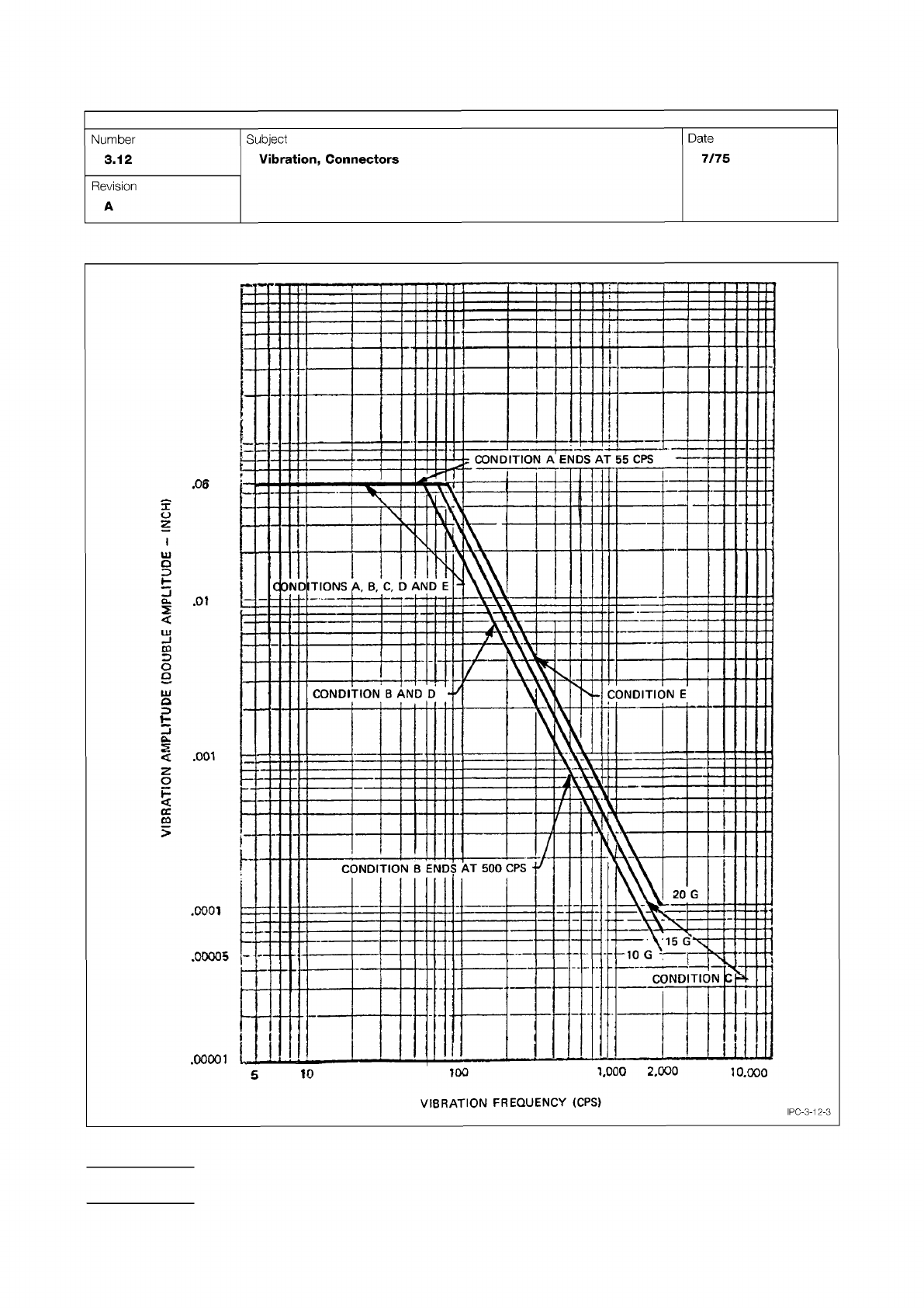
Figure 3 Vibration Test Curves
IPC-TM-650
Page 4 of 6
.0001
.00005
-
.00001
10
L000
2,000
10.000
VIBRATION
FREQUENCY
(CPS)
Number
3.12
Subject
Vibration,
Connectors
Date
7/75
Revision
A
1
00
^§5^
&mno
£
wwldwv
NOUVH
-
A
IPC-3-12-3
5.7.1.1
Place specimens in a chamber, in a vertical position
and under a condensation drip shield. Condition the speci-
mens at 50 ± 2 °C [122 ± 3.6 °F] with no added humidity, for
a period of 24 hours.
5.7.1.2
Allow the specimens to cool, measure and record
the initial insulation resistance measurements at ambient labo-
ratory conditions. Apply 100 VDC on the specimen’s test
points as specified in 3.1.1 or 3.2 with the resistance meter
and take the reading after one minute. See 6.2.
5.7.1.3
Connect the 50 VDC voltage source to each of the
specimens test points as indicated in 3.1.1 or 3.2. Each
chamber load shall contain at least one uncoated control
board that is representative of the cleaning process used prior
to solder mask application for each solder mask tested.
5.7.1.4
The test points for qualification tests are 1 to 2, 3 to
2, 3 to 4 and 5 to 4 on the D comb pattern. On the D comb
pattern, test points 1, 3 and 5 are connected to the positive
terminal and test points 2 and 4 are connected to the nega-
tive terminal of the resistance meter. For quality conformance,
the pair of test points is 1 to 2 on the C pattern. One side of
the C pattern should be connected to the negative terminal
and the other side to the positive.
5.7.1.5
Close chamber door and apply a 50 volt bias to all
comb patterns (D or C patterns) tested.
5.7.1.6
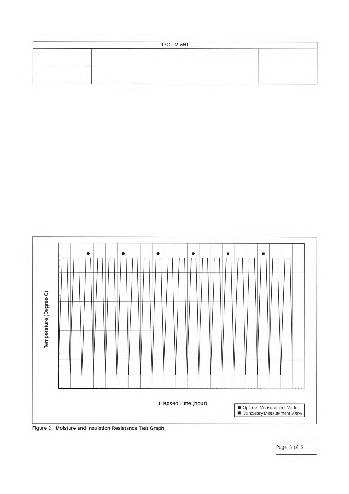
Expose test specimens to 20 cycles of temperature
and humidity (see Figure 2). The bias voltage shall be main-
tained throughout the entire 20-cycle period. Humidity shall be
maintained at 85% minimum through the cycles except when
going to low temperature (see step c below), in which case
the humidity may temporarily drop to 80% minimum.
One cycle is as follows:
a. Start test at 25 ± 2 °C [77 ± 3.6 °F] and raise the tempera-
ture to 65 ± 2 °C [149 °F] over a time span of 2.5 hours ±
5 minutes
0
20
30
40
50
60
70
8 16 24 32 40 48 56 64 72 80 88 96 104 112 120 128 136 144 152 160 168
Number
2.6.3.1
Subject
Solder Mask - Moisture and Insulation Resistance
Date
03/07
Revision
E
Elapsed
Time
(hour)
•
Optional
Measurement
Made
Mandatory
Measurement
Made
IPC-TM-650
—
6
dE
Figure
2
Moisture
and
Insulation
Resistance
Test
Graph
Page
3
of
5
b. Maintain temperature at 65 ± 2 °C [149 ± 3.6 °F] for 3,
+0.5/-0 hours
c. Lower the temperature from 65 ± 2 °C [149 ± 3.6 °F] to
25 ± 2 °C [77 ± 3.6 °F] over a time span of 2.5 hours ± 5
minutes
There shall be no delay between cycles.
5.7.2 Class H Measurement
5.7.2.1
Disconnect the 50 VDC bias voltage source before
taking the insulation resistance measurements. Electrical con-
nections to specimens shall be made such that the bias and
test voltages are of the same polarity. Insulation resistance
shall be read as specified in 5.7.1.4. Apply 100 VDC on the
specimens test points with the resistance meter and take the
reading after one minute with the patterns under test condi-
tions.
5.7.2.2
For qualification testing, measure and record resis-
tance once every 24 hours (if insulation resistance quality
measurements are required, see 5.7.3.1), between the 2nd
and 3rd hour of the high termperature phase of each cycle.
These measurements are to be conducted without opening
the chamber. After completion of the temperature cycling, dis-
connect the bias voltage, remove the specimens from the
chamber, and measure and record insulation resistance after
the specimen has been at ambient conditions for more than
one hour but less than two hours.
5.7.2.3
For conformance testing using pattern C, the mea-
surements should be taken after disconnectng the bias volt-
age, removing the specimens from the test chamber and
allowing the specimens to stabilize to laboratory ambient con-
ditions for one hour and not exceeding two hours. See 6.2.
5.7.3 Class H Evaluation
5.7.3.1
Each test specimen shall be evaluated for insulation
resistance quality following and/or during the stated condi-
tions. Although several insulation resistance readings may be
taken during the test, only the final (18th cycle) readings in
high temperature phase in the chamber and the reading taken
outside the chamber shall be used to determine pass/fail cri-
teria.
5.7.3.2
After completion of all electrical testing, the test
specimens shall be examined for blisters or delamination fol-
lowing the 24-hour stabilization at ambient laboratory condi-
tions. See 6.2.
5.8 Class T Procedures
5.8.1 Class T Testing
5.8.1.1
Condition the specimens at 50 ± 2 °C [122 ± 3.6 °F]
with no added humidity, for a period of 24 hours.
5.8.1.2
Remove the specimens from the oven and cool to
laboratory ambient temperature. Apply 100 VDC to comb pat-
terns E and F of each test specimen. See 6.2.
5.8.1.3
The test points for qualification are at each pair of
terminals (finger tabs) on the E and F comb patterns. One of
the test points is connected to the negative terminal and the
other to the positive terminal. For quality conformance, the
pair of test points is 1 to 2 on the C pattern. One side of the
C pattern should be connected to the negative terminal and
the other side to the positive.
5.8.1.4
Place the specimens in the test chamber in the ver-
tical position and under a condensation drip shield.
Each chamber load shall contain at least one
uncoated board that is representative of the cleaning process
used prior to solder mask application for each solder mask
tested.
5.8.1.5
Close the chamber door and bring the chamber to
65 ± 2 °C [149 ± 3.6 °F] and 90% relative humidity.
5.8.1.6
Allow specimens to stabilize at test conditions for 24
hours.
5.8.2 Class T Measurement
5.8.2.1
Connect the resistance meter to the appropriate test
points. For qualification testing, one of the test points of the
two terminal E and F patterns are connected to the negative
terminal and the other test point to the positive. For quality
conformance testing, one side of the C pattern (‘‘Y’’ pattern)
should be connected to the negative terminal and the other
side to the positive.
5.8.2.2
Apply 100 VDC on the specimens test points with
the resistance meter and take the reading after one minute
with the patterns under test conditions.
Number
2.6.3.1
Subject
Solder Mask - Moisture and Insulation Resistance
Date
03/07
Revision
E
IPC-TM-650
—
Note:
NOTE:
Other
readings
are
optional
and
may
be
used
for
diagnostic
information
or
aborting
the
test.
Page
4
of
5