IPC-TM-650 EN 2022 试验方法--.pdf - 第68页
The Institute for Int erconnecting and Packaging E lectronic Circuits 2215 S anders Road • Northbrook, IL 60062-6135 Material in this T est M ethods Manual was vol untaril y establis hed by T echni cal Committees of the …
The Institute for Interconnecting and Packaging Electronic Circuits
2215 Sanders Road • Northbrook, IL 60062-6135
Material in this Test Methods Manual was voluntarily established by Technical Committees of the IPC. This material is advisory only
and its use or adaptation is entirely voluntary. IPC disclaims all liability of any kind as to the use, application, or adaptation of this
material. Users are also wholly responsible for protecting themselves against all claims or liabilities for patent infringement.
Equipment referenced is for the convenience of the user and does not imply endorsement by the IPC.
Page 1 of 1
IPC-TM-650
TEST
METHODS
MANUAL
1
.0
Scope
1.1
This
method
describes
the
procedure
required
to
exam¬
ine
materials
and/or
finished
product
for
workmanship,
which
is
the
general
quality
of
the
goods
other
than
as
specified
by
the
applicable
standard.
2
.0
Applicable
Documents
3
.0
Test
Specimens
3.1
Any
piece
of
a
lot
is
subject
to
examination.
Generally,
those
specimens
prepared
for
inspection
and/or
testing
for
specific
properties
may
be
used
to
determine
workmanship.
4
.0
Apparatus
or
Material
4.1
Referee
optical
device
-
10X
magnification.
5
.0
Procedure
Number
2.1.8
Subject
Workmanship
Date
Revision
12/94
B
Originating
Task
Group
MIL-P-13949
Test
Methods
Task
Group
(7-1
1b)
5.1.1
At
any
stage
of
product
handling,
sample
preparation,
or
specimen
conditioning,
the
product
shall
be
under
scrutiny
for
detection
of
any
defects,
flaws,
or
unusual
characteristics
other
than
those
specifically
called
out
in
the
applicable
speci¬
fication,
using
unaided
or
corrected
20/20
vision.
5.1.2
In
the
case
of
a
questionable
evaluation
with
20/20
vision,
a
referee
inspection
shall
be
made
using
the
10X
mag¬
nification.
5.2
Record
and
Report
5.2.1
Each
incidence
of
suspect
flaw
or
defect
shall
be
noted
and
documented.
The
authorized
quality
function
shall
determine
whether
the
reliability,
serviceability,
or
functionality
of
the
product
may
be
affected.
5.2.2
Record
and
report
findings,
including
photographs
of
defect,
if
deemed
necessary.
5.1
Evaluation
6.0
Notes
None
The Institute for Interconnecting and Packaging Electronic Circuits
2215 Sanders Road • Northbrook, IL 60062-6135
Material in this Test Methods Manual was voluntarily established by Technical Committees of the IPC. This material is advisory only
and its use or adaptation is entirely voluntary. IPC disclaims all liability of any kind as to the use, application, or adaptation of this
material. Users are also wholly responsible for protecting themselves against all claims or liabilities for patent infringement.
Equipment referenced is for the convenience of the user and does not imply endorsement by the IPC.
Page 1 of 1
IPC-TM-650
TEST
METHODS
MANUAL
1
.0
Scope
To
visually
locate,
and
by
feel,
evaluate
surface
scratches
during
visual
inspection.
If
more
exacting
data
is
required
for
referee
evaluations
of
microsectioning
per
IPC-TM-650,
Method
2.1
.1
shall
be
used.
2
.0
Applicable
Documents
None.
3
.0
Test
Specimen
Any
qualified
submitted
sheet(s)
or
cut
to
size
panel(s)
or
periodic
quality
conformance
specimens.
4
.0
Apparatus
Dunlop
Tortex
guitar
pick
1
.00
mm
thick¬
ness
or
equivalent.
5
.0
Procedures
5.1
Test
Number
2.1.9
Subject
Surface
Scratch
Examination
Metal-Clad
Foil
Date
Revision
5/86
Originating
Task
Group
N/A
5.1.1
Locate
scratches
visually
using
normal
or
corrected
20/20
vision.
5.1.2
Scratches
which
stop
the
pick
when
light
pressure
is
applied
are
unacceptable.
Scratches
which
can
be
felt
by
the
pick
but
do
not
stop
it
are
acceptable.
5.1.3
The
referee
test
shall
be
by
microsection
per
IPC-TM-
650,
Method
2.1.1.
5.2
Evaluation
5.2.1
Evaluate
in
the
“working
area”
of
the
sheet
or
panel.
Working
area
excludes
a
1
in.
border
on
all
four
edges.
Compare
results
with
inspection
represented
in
the
appropri¬
ate
specification.
IPC-TM-650
Number
Subject Date
Revision
Page 2 of 2
2.2.4
Dimensional
Stability,
Flexible
Dielectric
Materials
5/98
C
Twenty-four
hour
stabilization
is
referee
method.
5.2
Method
A
Dimensional
stability
of
unclad
material
due
to
thermal
exposure
—
standard
condition.
(1)
Place
test
specimen
unconstrained
in
an
oven
maintained
at
150℃
±
2
℃
for
30
±
2
minutes.
(2)
Cool
specimen
to
standard
conditions
of
23℃
±
2
℃
and
50%
±
5%
RH
for
24
hours
minimum
(see
5).
(3)
Remeasure
separation
of
holes/lines
and
record
as
final
measurement
after
thermal
exposure
(F).
5.3
Method
B
Dimensional
stability
of
metal
clad
dielectrics
due
to
metal
removal.
(1)
Chemically
erode
the
metal
away
except
for
the
target
areas,
which
can
have
up
to
13
mm
x
13
mm
square
metal,
using
an
etchant
that
has
no
detrimental
effect
on
either
the
dielectric
or
adhesive.
Wash
and
dry.
The
test
specimen
should
be
unconstrained
during
the
etching,
washing,
and
drying
operation.
(2)
Stabilize
test
specimen
for
24
hours
at
23℃
±
2
℃
and
50%
±
5%
RH
(see
5.1).
(3)
Remeasure
separation
of
holes/lines
and
record
as
final
measurement
after
etching
(F2).
5.4
Method
C
Dimensional
stability
of
dielectric
due
to
thermal
exposure
and
metal
removal,
using
specimens
from
Method
B.
Place
unconstrained
etched,
conditioned,
and
measured
specimen
from
Method
B
in
an
oven
maintained
at
150℃
土
2
℃
for
30
±
2
minutes.
(2)
Stabilize
specimen
at
23℃
±
2
℃
and
50%
±
5%
RH
for
24
hours
and
remeasure
separation
of
holes
(see
5.1).
(3)
Remeasure
separation
of
holes/lines
and
record
as
final
after
etching
and
thermal
exposure
(F3).
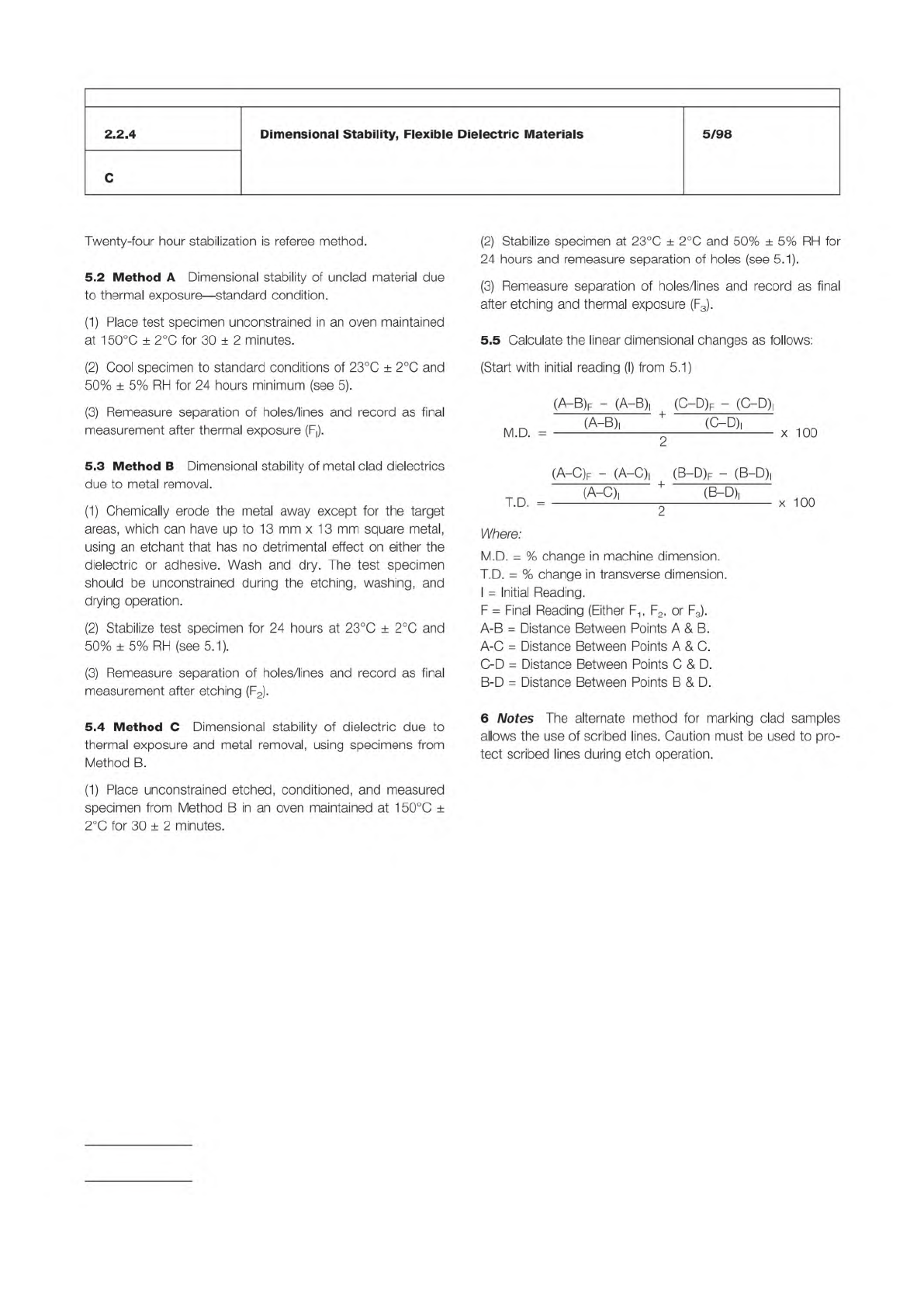
5.5
Calculate
the
linear
dimensional
changes
as
follows:
(Start
with
initial
reading
(I)
from
5.1)
(A—B)f
-
(A-B)|
(O-D)F
-
(C-D)|
,八
c、
+
e
c、
(A-C)f
-
(
A-C)|
(B-D)f
-
(
B-D)|
(A-C)|
*
(B-D)!
I
.U.
—
2
Where:
M.D.
=
%
change
in
machine
dimension.
T.D.
=
%
change
in
transverse
dimension.
I
=
Initial
Reading.
F
二
Final
Reading
(Either
F1
,
F2,
or
F3).
A-B
=
Distance
Between
Points
A
&
B.
A-C
=
Distance
Between
Points
A
&
C.
C-D
=
Distance
Between
Points
C
&
D.
B-D
=
Distance
Between
Points
B
&
D.
6
Notes
The
alternate
method
for
marking
clad
samples
allows
the
use
of
scribed
lines.
Caution
must
be
used
to
pro¬
tect
scribed
lines
during
etch
operation.
x
100
x
100