IPC-TM-650 EN 2022 试验方法--.pdf - 第686页
Material in this T est M ethods Manual was voluntarily establis hed by T echni cal Committees of IPC. Thi s mat erial is a dvisory only and its use or adaptation is entirely voluntary . IPC disclaims all lia bility of an…
IPC-TM-650
Page 2 of 2
Number
2.6.4
Subject
Outgassing,
Printed
Boards
Date
05/04
Revision
B
5.4
Exposure
5.4.1
Prior
to
operation,
all
temperature-vacuum
apparatus
such
as
the
heating
bar,
separators,
and
cooling
plates
shall
be
clean
and
aligned.
5.4.2
Place
the
test
specimen
and
boat
into
the
specimen
compartment
in
the
temperature-vacuum
system.
Mount
the
respective
cover
plates
of
each
specimen
compartment
and
at
least
three
(3)
control
compartments.
5.4.3
Close
and
activate
the
vacuum
system
and
allow
the
system
to
evacuate
to
7.0
X
10-3
Pa
(5
X
10-5
Torr)
or
less
within
one
hour.
During
this
period,
control
of
the
collector
plate
temperature
at
25
±
1
[77
°F
±
2
°F]
shall
be
achieved.
5.4.4
When
the
required
vacuum
has
been
achieved,
turn
on
the
heater
bar
and
adjust
the
controller
to
heat
the
bar
to
125
℃
±
1
℃
[257
°F
±
2
°F]
within
60
minutes.
5.4.5
Maintain
the
collector
plate
temperatures
at
25
±
1
[77
°F
±
2
°F]
and
the
heater
bar
temperature
at
125
土
1
[257
°F
±
2
°F]
for
24
hours.
After
this
time
period
close
the
vacuum
valve
to
the
pumping
system
and
turn
off
the
cur¬
rent
to
the
heater
bars.
5.4.6
Open
the
vent
valve
and
backfill
with
clean,
dry
nitro¬
gen
at
a
gage
pressure
of
10
to
30
kPa
(2
to
4
psi)
above
atmosphere
to
rapidly
cool
the
bars
to
50
[1
22
°F]
within
two
hours,
nominally.
5.4.7
Turn
off
the
collector-plate
heat
exhchangers,
return
the
vacuum
chamber
to
room
pressure
using
clean,
dry
nitro¬
gen,
and
open
the
chamber.
Remove
the
aluminum
specimen
boats
and
their
respective
collector
plates
and
the
control
col¬
lector
plates
and
immediately
store
in
the
dry
desiccator
(see
4.3).
5.4.8
After
allowing
the
specimens
to
cool
to
approximately
room
temperature,
but
after
no
more
than
1/2
hour,
weigh
the
specimens
and
boats
and
the
collector
plates
to
the
nearest
1
microgram
within
two
minutes
of
removal
from
the
desicca¬
tors.
5.5
Evaluation
of
Test
5.5.1
Measurements
of
the
control
collector
plates
are
used
to
detect
contamination
and/or
poor
technique.
Mass
loss
of
greater
than
20
micrograms
is
an
indication
of
poor
cleaning
of
the
collector
plates.
Mass
gain
of
greater
than
50
micro¬
grams
is
an
indication
of
poor
cleaning
of
elements
of
the
apparatus,
cross
contamination
between
specimen
compart¬
ments,
or
poor
vacuum
technique.
Any
change
of
50
micro¬
grams
or
greater
calls
for
a
review
of
or
change
in
technique.
All
data
obtained
during
such
runs
shall
be
discarded
and
the
test
rerun
when
the
system(s)
are
corrected.
5.5.2
Calculation
of
Total
Mass
Loss
(TML).
Calculate
the
TML
as
follows:
Initial
Mass
Final
Mass
Specimens
Weights:
S
=
+
B)
-
B
Sf
二
(SF
+
B)
-
B
Mass
Loss
(L)
=
S,
-
SF
Total
Mass
Loss
(TML)
(%)
二
(
L/S)
X
100
Where:
B
=
Mass
of
boat
in
grams
S|
=
Initial
specimen
mass
in
grams
SF
二
Final
Specimen
mass
in
grams
L
=
Mass
Loss
in
grams
5.5.3
Calculate
the
Collected
Condensable
Volatile
Material
(CVCM)
as
follows:
Mass
of
condensable
material
(Co)
二
CF
-
C,
CVCM
(%)
=
(CJS)
X
100
Where:
CF
二
Final
mass
of
collector
plate
in
grams
C|
=
Initial
mass
of
collector
plate
in
grams
Co
二
Mass
of
condensable
material
in
grams
S|
=
Initial
specimen
mass
in
grams
6
Notes
6.1
A
useful
outgassing
test
data
sheet
format
can
be
found
in
Appendix
X1
of
ASTM
E
595.
6.2
Additional
information
regarding
this
test
method
and
suggested
requirements
for
certain
spacecraft
applications
can
be
found
in
NASA
SP-R-0022.
Material in this Test Methods Manual was voluntarily established by Technical Committees of IPC. This material is advisory only
and its use or adaptation is entirely voluntary. IPC disclaims all liability of any kind as to the use, application, or adaptation of this
material. Users are also wholly responsible for protecting themselves against all claims or liabilities for patent infringement.
Equipment referenced is for the convenience of the user and does not imply endorsement by IPC.
Page 1 of 1
r
ASSOCIATION
CONNECTING
/
ELECTRONICS
INDUSTRIES
®
221
5
Sanders
Road
Northbrook,
IL
60062-6135
IPC-TM-650
TEST
METHODS
MANUAL
1
Scope
This
method
is
to
determine
the
electrical
perfor¬
mance
of
multilayer
printed
wiring
boards
by
following
the
shock
with
an
electrical
continuity
test
as
specified.
2
Applicable
Documents
None
3
Test
Specimen
Complete
multilayer
printed
wiring
board
or
qualification
test
board
IPC-A-47.
4
Apparatus
4.1
A
standard
AVCO
150
pneumatic
drop
shock
tester,
or
equivalent,
capable
of
attaining
at
least
1
50
Gs.
4.2
High-speed
motion
picture
and
oscilloscope
photogra¬
phy
is
not
normally
necessary
and
is
not
recommended
for
the
average
“go
no-go"
testing
program.
Number
2.6.5
Subject
Physical
Shock,
Multilayer
Printed
Wiring
Originating
Task
Group
Rigid
Printed
Board
Performance
Task
Group
(D-33a)
Date
Revision
05/04
D
5
Procedure
5.1
Preparation
Fixture
the
test
pattern
boards
so
they
are
restrained
on
all
four
edges.
Fabricate
the
fixtures
so
that
it
can
be
oriented
to
test
the
boards
on
three
principle
planes.
5.2
Test
Subject
each
specimen
to
three
shock
pulses
of
100
Gs
with
a
duration
of
6.5
milliseconds
in
each
of
the
three
principle
planes
—
a
total
of
nine
blows.
5.3
Evaluation
Subject
each
specimen
to
a
continuity
test
as
specified.
6
Notes
None
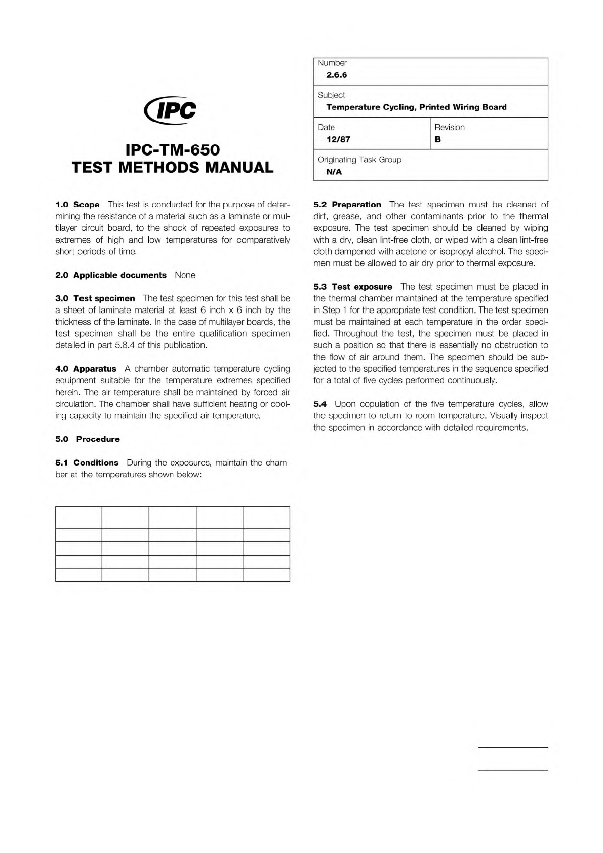
Class A Class B
Step
Temp.
(°C)
Time
(Min.)
Temp.
(°C)
Time
(Min.)
1 125+3/–0 30 85+3/–0 30
2 25+10/–5 10–15 25+10/–5 10–15
3 –65+0/–5 30 –55+0/–5 30
4 25+10/–5 10–15 25+10/–5 10–15
The Institute for Interconnecting and Packaging Electronic Circuits
2215 Sanders Road • Northbrook, IL 60062-6135
Material in this Test Methods Manual was voluntarily established by Technical Committees of the IPC. This material is advisory only
and its use or adaptation is entirely voluntary. IPC disclaims all liability of any kind as to the use, application, or adaptation of this
material. Users are also wholly responsible for protecting themselves against all claims or liabilities for patent infringement.
Equipment referenced is for the convenience of the user and does not imply endorsement by the IPC.
Page 1 of 1
IPC-TM-650
TEST
METHODS
MANUAL
1
.0
Scope
This
test
is
conducted
for
the
purpose
of
deter¬
mining
the
resistance
of
a
material
such
as
a
laminate
or
mul¬
tilayer
circuit
board,
to
the
shock
of
repeated
exposures
to
extremes
of
high
and
low
temperatures
for
comparatively
short
periods
of
time.
2
.0
Applicable
documents
None
3
.0
Test
specimen
The
test
specimen
for
this
test
shall
be
a
sheet
of
laminate
material
at
least
6
inch
x
6
inch
by
the
thickness
of
the
laminate.
In
the
case
of
multilayer
boards,
the
test
specimen
shall
be
the
entire
qualification
specimen
detailed
in
part
5.8.4
of
this
publication.
4
.0
Apparatus
A
chamber
automatic
temperature
cycling
equipment
suitable
for
the
temperature
extremes
specified
herein.
The
air
temperature
shall
be
maintained
by
forced
air
circulation.
The
chamber
shall
have
sufficient
heating
or
cool¬
ing
capacity
to
maintain
the
specified
air
temperature.
5
.0
Procedure
Number
2.6.6
Subject
Temperature
Cycling,
Printed
Wiring
Board
Date
Revision
12/87
B
Originating
Task
Group
N/A
5.2
Preparation
The
test
specimen
must
be
cleaned
of
dirt,
grease,
and
other
contaminants
prior
to
the
thermal
exposure.
The
test
specimen
should
be
cleaned
by
wiping
with
a
dry,
clean
lint-free
cloth,
or
wiped
with
a
clean
lint-free
cloth
dampened
with
acetone
or
isopropyl
alcohol.
The
speci¬
men
must
be
allowed
to
air
dry
prior
to
thermal
exposure.
5.3
Test
exposure
The
test
specimen
must
be
placed
in
the
thermal
chamber
maintained
at
the
temperature
specified
in
Step
1
for
the
appropriate
test
condition.
The
test
specimen
must
be
maintained
at
each
temperature
in
the
order
speci¬
fied.
Throughout
the
test,
the
specimen
must
be
placed
in
such
a
position
so
that
there
is
essentially
no
obstruction
to
the
flow
of
air
around
them.
The
specimen
should
be
sub¬
jected
to
the
specified
temperatures
in
the
sequence
specified
for
a
total
of
five
cycles
performed
continuously.
5.4
Upon
copulation
of
the
five
temperature
cycles,
allow
the
specimen
to
return
to
room
temperature.
Visually
inspect
the
specimen
in
accordance
with
detailed
requirements.
5.1
Conditions
During
the
exposures,
maintain
the
cham¬
ber
at
the
temperatures
shown
below: