IPC-TM-650 EN 2022 试验方法--.pdf - 第690页
IPC-CC-830 Class Low T emperature High T emperature Figure 1 IPC -B-25A T est Board Material in this T est M ethods Manual was voluntarily establis hed by T echni cal Committees of IPC. Thi s mat erial is a dvisory only …
Table 1
Step
Test Condition A Test Condition B Test Condition C
Temperature Time Temperature Time Temperature Time
1
2
3
4
0, +0/-5
25, +10/-5
+70, +5/-0
25, +10/-5
15
0
15
0
-40, +0/-5
25, +10/-5
+85, +5/-0
25, +10/-5
15
0
15
0
-55, +0/-5
25, +10/-5
+105, +5/-0
25, +10/-5
15
0
15
0
Step
Test Condition D Test Condition E Test Condition F
Temperature Time Temperature Time Temperature Time
1
2
3
4
-55, +0/-5
25, +10/-5
+125, +5/-0
25, +10/-5
15
0
15
0
-65, +0/-5
25, +10/-5
+150, +5/-0
25, +10/-5
15
0
15
0
-65, +0/-5
25, +10/-5
+170, +5/-0
25, +10/-5
15
0
15
0
Tolerance shall be +2 and -0 minutes.
Table 2
Rigid Type NEMA Test Condition
A
GP, GT, GX, GY B
GE C
AF, BF, BI, CF, GF, GB D
GH, GM E
AI, GI, QI F
IPC-TM-650
Number
Subject Date
Revision
Page 2 of 2
2.6.7
Thermal
Shock
&
Continuity,
Printed
Board
8/97
A
6.1.1
Unless
otherwise
specified
by
the
applicable
perfor¬
mance
specification,
the
following
base
material
types/
temperature
ratings
are
recommended.
6.2
Suggested
sources
for
capable
test
equipment:
Cambridge
Technology
Model
51
OA
Micro-Ohmmeter
23
Elm
Street
Watertown,
MA
02172
(617)
923-1181
Hewlett-Packard
Model
4338A
Milliohmmeter
9800
Muirlands
Avenue
Irvine,
CA
92718
(714)
472-3000
Keithly
Instruments
Model
580
Micro-ohmmeter
28775
Aurora
Road
Cleveland,
OH
44139
(800)
552-1115
IPC-CC-830
Class Low Temperature High Temperature
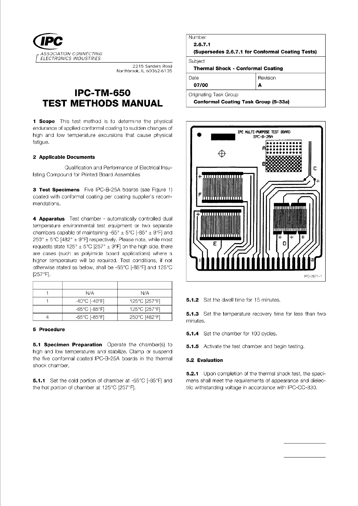
Figure 1 IPC-B-25A Test Board
Material in this Test Methods Manual was voluntarily established by Technical Committees of IPC. This material is advisory only
and its use or adaptation is entirely voluntary. IPC disclaims all liability of any kind as to the use, application, or adaptation of this
material. Users are also wholly responsible for protecting themselves against all claims or liabilities for patent infringement.
Equipment referenced is for the convenience of the user and does not imply endorsement by IPC.
Page 1 of 1
ASSOCIATION
CONNECTING
/
ELECTRONICS
INDUSTRIES
221
5
Sanders
Road
Northbrook,
IL
60062-61
35
IPC-TM-650
TEST
METHODS
MANUAL
1
Scope
This
test
method
is
to
determine
the
physical
endurance
of
applied
conformal
coating
to
sudden
changes
of
high
and
low
temperature
excursions
that
cause
physical
fatigue.
2
Applicable
Documents
Qualification
and
Performance
of
Electrical
Insu¬
lating
Compound
for
Printed
Board
Assemblies
3
Test
Specimens
Five
IPC-B-25A
boards
(see
Figure
1)
coated
with
conformal
coating
per
coating
supplier's
recom¬
mendations.
4
Apparatus
Test
chamber
-
automatically
controlled
dual
temperature
environmental
test
equipment
or
two
separate
chambers
capable
of
maintaining
-65°
±
5
℃
[-85°
±
9°F]
and
250°
土
5
℃
[482°
土
9°F]
respectively.
Please
note,
while
most
requests
state
125°
±
5
℃
[257。
±
9°F]
on
the
high
side,
there
are
cases
(such
as
polyimide
board
applications)
where
a
higher
temperature
will
be
required.
Test
conditions,
if
not
otherwise
stated
as
below,
shall
be
-65℃
[-85°F]
and
125℃
[257°F].
1
N/A N/A
2
-40℃
[-40°F]
125℃
[257°F]
3
-65℃
[-85°F]
125℃
[257°F]
4
-65℃
[-85°F]
250℃
[482°F]
5
Procedure
5.1
Specimen
Preparation
Operate
the
chamber(s)
to
high
and
low
temperatures
and
stabilize.
Clamp
or
suspend
the
five
conformal
coated
IPC-B-25A
boards
in
the
thermal
shock
chamber.
5.1.1
Set
the
cold
portion
of
chamber
at
-65℃
[-85°F]
and
the
hot
portion
of
chamber
at
125℃
[257°F].
Number
2.6.7.1
(Supersedes
2.6.7.
1
for
Conformal
Coating
Tests)
Subject
Thermal
Shock
-
Conformal
Coating
Date
07/00
Revision
A
Originating
Task
Group
Conformal
Coating
Task
Group
(5-33a)
5.1.2
Set
the
dwell
time
for
15
minutes.
5.1.3
Set
the
temperature
recovery
time
for
less
than
two
minutes.
5.1.4
Set
the
chamber
for
100
cycles.
5.1.5
Activate
the
test
chamber
and
begin
testing.
5.2
Evaluation
5.2.1
Upon
completion
of
the
thermal
shock
test,
the
speci¬
mens
shall
meet
the
requirements
of
appearance
and
dielec¬
tric
withstanding
voltage
in
accordance
with
IPC-CC-830.
1 Scope and Purpose
1.1 Scope
This method subjects unpopulated test speci-
mens (samples) to sudden, extreme changes in temperature
in order to evaluate the quality of interconnects formed during
the manufacturing processes.
1.2 Purpose
This method be used to simulate the
thermodynamic effects of extreme temperature variations. The
use of this method is intended to be able to capture ‘‘infant
mortality’’ types of manufacturing defects.
1.2.1
This method may provide for qualification, quality con-
formance testing and lot acceptance.
2 Applicable Documents
Terms and Definitions
Generic Standard on Printed Board Design
Acceptability of Printed Boards
Standard for Printed Board Handling and Storage
Specification for Base Materials for Rigid and Mul-
tilayer Printed Boards
Specification for Base Materials for High Speed/
High Frequency Applications
Qualification and Performance Specification for
Rigid Printed Boards
Qualification and Performance Specification for
Flexible Printed Boards
Qualification and Performance Specification for
High Frequency (Microwave) Printed Boards
Guidelines for Microsection Preparation
Test Methods Manual
1
2.1.1 Microsectioning - Microsectioning, Manual and Semi
or Automatic Method
2.6.27 Assembly Simulation - Thermal Stress, Convection
Reflow Assembly Simulation
3 Terms and Definitions
3.1 Thermal Shock (Unpopulated Printed Board)
A tem-
perature cycle with a change rate of 1 °C or more per second
as measured on the surface of the test specimen, for at least
the center 60% of each transition, during the heating and
cooling portions.
3.2 Thermal Cycle (Unpopulated Printed Board)
A tem-
perature cycle that has a sample change rate of less than 1 °C
per second as measured on the surface of the test specimen,
for at least the center 60% of each transition, during the heat-
ing and cooling portions. While no minimum temperature
change rate is specified, a change rate of at least 10 °C per
minute is expected for qualification testing.
4 Test Specimen
4.1 Design/Construction Criteria
4.1.1
The test specimen be the D coupon in accor-
dance with the requirements of IPC-2221 Appendix A, or
alternate coupon(s) AABUS.
4.1.2
The test specimen(s) be constructed with holes
contained in the printed board it represents as follows:
• Through holes: D coupons
be constructed with both
the largest plated-through holes (PTHs) and the smallest
plated-through vias.
• Propagated structures: D coupons
be constructed
with and represent all applicable blind, buried, or filled
through hole (propagated) via structures as defined in IPC-
2221 Appendix A. D coupons contain two nets (structures).
Multiple D coupons are used for designs with more than two
structures.
4.1.2.1
The test specimen(s) contain the representa-
tive ground and power planes of the printed board design.
4.1.3
The test specimen(s) allow for microsection
evaluation of all the applicable, representative PTHs and vias
defined in 4.1.2 after exposure to the conditions of this Test
Method. IPC-9241 provides guidance on the proper prepara-
tion of a metallographic sample (microsection) of a printed
board.
3000 Lakeside Drive, Suite 105N
Bannockburn, IL 60015-1249
IPC-TM-650
TEST METHODS MANUAL
Number
2.6.7.2
Subject
Thermal Shock, Thermal Cycle and Continuity
Date
3/2020
Revision
C
Originating Task Group
Thermal Stress Test Methodology Subcommittee
(D-32)
Association
Connecting
Electronics
Industries
shall
IPC-T-50
IPC-2221
IPC-A-600
IPC-1601
IPC-4101
IPC-4103
IPC-6012
IPC-6013
IPC-6018
IPC-9241
IPC-TM-650
shall
shall
shall
shall
shall
shall
Material
/n
this
Test
Methods
Manual
was
voluntarily
established
by
Technical
Committees
of
I
PC.
This
material
/s
advisory
only
and
"s
use
or
adaptation
,
s
entirely
voluntary.
IPC
disclaims
all
liability
of
any
kind
as
to
the
use,
application,
or
adaptation
of
this
material.
Users
are
also
wholly
responsible
for
protecting
themselves
against
all
claims
or
liabilities
for
patent
infringement.
Equipment
referenced
/s
for
the
convenience
of
the
user
and
does
not
imply
endorsement
by
IPC.
Page
1
of
5