IPC-TM-650 EN 2022 试验方法--.pdf - 第695页
7 Notes 7.1 The design of the thermal cycling system must be flex- ible enough to allow for an extreme ly high rate of temperature change and f or the rate of temper ature change to be deter- mined. Some issues to c on s…
• -40 °C
• -55 °C (default)
• -65 °C
6.5.1.3 Tolerances
The tolerance associated with the hot
cycle is +/-5 °C. The tolerance associated with the cold cycle
is +/-5 °C.
6.5.1.4 Dwell Time at Extremes
During each cycle, the
test specimen(s)
be subjected to each temperature
extreme for the time required for stabilization plus time
required to record all measurements (up to 15 minutes when
a dual chamber is used).
6.5.2 Temperature Change Rate
The rate of change
between temperature extremes, both high to low and low to
high,
be as high as possible. The temperature change
be at least 1 °C per second for at least the center 60%
of each transition period, hot to cold and cold to hot. Note
that for thicker coupons greater than 2.5 mm [0.100 in], this
change rate may not be achievable.
6.5.2.1 Temperature Documentation
6.5.2.1.1
The temperature of a representative test speci-
men
be recorded at the end of the dwell at each tem-
perature extreme, for every cycle.
6.5.2.1.2
A temperature profile from at least one complete
cycle
be recorded during each test and included in the
test report. This
include the temperatures of a
representative test specimen and the hot/cold media. The
temperatures
be taken at sufficient frequency to show
compliance to 5.5.1 and 6.5.1.3. Recording data every sec-
ond for this purpose is recommended.
6.6 Testing Summary
A summary of Qualification and Quality Conformance testing
is listed below in Table 6-2.
6.7 Evaluation
6.7.1 Resistance Change
The change in resistance
between the first and each succeeding temperature cycle
be determined. The maximum allowable percent change
in resistance between the first and any subsequent cycle
be 5% unless otherwise specified.
6.7.2 Results
Test results including cycles to failure, corre-
sponding percent change of the failure, and the percent
change of the final cycle
be documented.
6.8 Deviations
Deviations to the stated requirements or
additional requirements defined here
be AABUS.
Conditioning 6 hours minimum, 105 - 125 °C
Reflow Simulation 6 cycles, 230, 245 or 260 °C profile
Temperature Min AABUS -40 °C, -55 °C (default), -65 °C
Temperature Max AABUS min. of:
T
g
-10 °C
Reflow peak -25 °C
210 °C
Sample Change Rate
> 10 °C/min for both hot and
cold
> 1 °C/sec for both hot and cold
Number of Cycles AABUS 100
Failure Threshold AABUS 5%
Resistance Data 1 reading/cycle near the end of the high temperature dwell
Temperature Data
1 reading/cycle near the end of the high and low temperature dwells (sample)
1 reading/sec through 1 complete cycle (sample and media)
Acceptance testing and quality conformance testing as described in IPC-6010 series printed board performance specifications.
Number
2.6.7.2
Subject
Thermal Shock, Thermal Cycle and Continuity
Date
3/2020
Revision
C
IPC-TM-650
shall
shall
shall
shall
shall
shall
shall
shall
shall
shall
shall
Table
6-2
Comparison
of
Qualification
and
Quality
Conformance
Testing
Note
1.
Item
Qualification
Quality
Conformance
/
Acceptance
Testing1
—
Page
4
of
5
7 Notes
7.1
The design of the thermal cycling system must be flex-
ible enough to allow for an extremely high rate of temperature
change and for the rate of temperature change to be deter-
mined. Some issues to consider are as follows:
• Thermal mass compensation capability (energy vs. time)
• Environmental control capability (heating and cooling)
• Reproducibility of parameters
• Transfer speed (if applicable)
• Heating ramp rate
• Cool down rate
• Programming capability
• Profile memory
7.2 Suggested Drawing Note
As this method addresses
assembly issues with printed boards, it is recommended that
the user of the printed board establish a drawing note in the
procurement documentation to provide the printed board fab-
ricators with guidance relative to the intended reflow process
of the printed board. An example of such a drawing note is
provided as follows:
XX. IPC D COUPON TESTING
A. COUPONS SHALL INCLUDE COMPONENT (A), VIA (B)
AND ALL PROPAGATED B STRUCTURES IAW IPC-
2221B APPENDIX A.
OF EACH COUPON DESIGN
BE TESTED PER MANUFACTURING PANEL.
B. THE IPC D COUPONS
BE SUBJECTED TO 6
REFLOW SIMULATIONS IAW IPC-TM-650, METHOD
2.6.27 USING THE [
]
PROFILE. ACCEPTANCE CRITERIA
BE < 5%
CHANGE IN RESISTANCE.
C. AFTER REFLOW SIMULATION TESTING, THE IPC D
COUPONS
BE SUBJECTED TO 100 THERMAL
SHOCKS IAW IPC-TM-650, METHOD 2.6.7.2 FROM
-55C TO [MINIMUM OF (
), OR
(
), OR
]. ACCEPTANCE CRITERIA BE < 5%
CHANGE IN RESISTANCE.
Parameters in should be tailored to each
application.
Number
2.6.7.2
Subject
Thermal Shock, Thermal Cycle and Continuity
Date
3/2020
Revision
C
IPC-TM-650
—
2
SHALL
SHALL
230
℃
,
OR
245
°C,
OR
260
SHALL
SHALL
LAMINATE
TG
-
10
REFLOW
PEAK
TEMPERATURE
-
25
210
SHALL
Note:
bold
Page
5
of
5
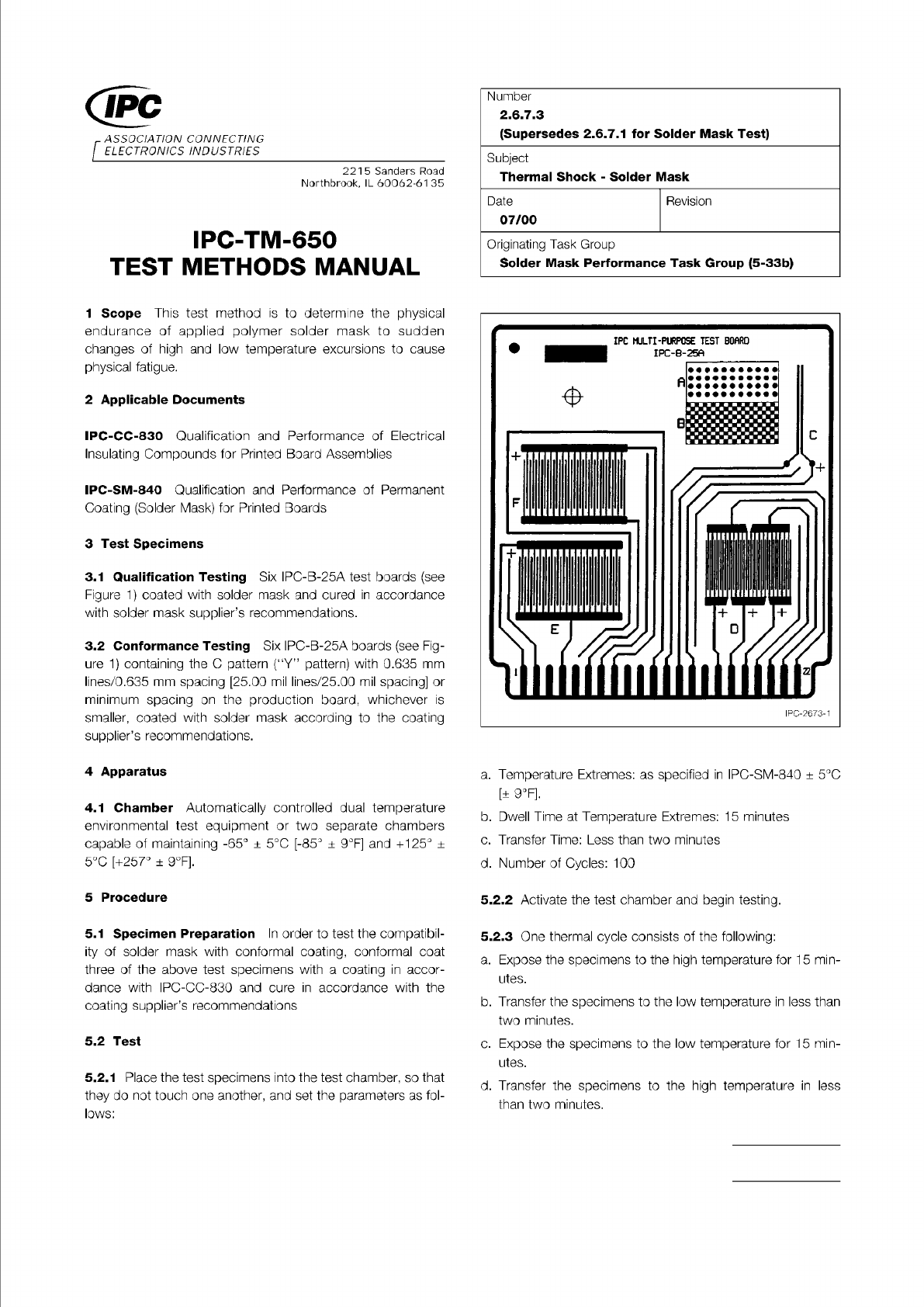
Figure 1 IPC-B-25A Test Board
Material in this Test Methods Manual was voluntarily established by Technical Committees of IPC. This material is advisory only
and its use or adaptation is entirely voluntary. IPC disclaims all liability of any kind as to the use, application, or adaptation of this
material. Users are also wholly responsible for protecting themselves against all claims or liabilities for patent infringement.
Equipment referenced is for the convenience of the user and does not imply endorsement by IPC.
Page 1 of 2
ASSOCIATION
CONNECTING
/
ELECTRONICS
INDUSTRIES
221
5
Sanders
Road
Northbrook,
IL
60062-61
35
IPC-TM-650
TEST
METHODS
MANUAL
1
Scope
This
test
method
is
to
determine
the
physical
endurance
of
applied
polymer
solder
mask
to
sudden
changes
of
high
and
low
temperature
excursions
to
cause
physical
fatigue.
2
Applicable
Documents
IPC-CC-830
Qualification
and
Performance
of
Electrical
Insulating
Compounds
for
Printed
Board
Assemblies
IPC-SM-840
Qualification
and
Performance
of
Permanent
Coating
(Solder
Mask)
for
Printed
Boards
3
Test
Specimens
3.1
Qualification
Testing
Six
IPC-B-25A
test
boards
(see
Figure
1)
coated
with
solder
mask
and
cured
in
accordance
with
solder
mask
supplier's
recommendations.
3.2
Conformance
Testing
Six
IPC-B-25A
boards
(see
Fig¬
ure
1)
containing
the
C
pattern
("Y”
pattern)
with
0.635
mm
lines/0.635
mm
spacing
[25.00
mil
lines/25.00
mil
spacing]
or
minimum
spacing
on
the
production
board,
whichever
is
smaller,
coated
with
solder
mask
according
to
the
coating
supplier's
recommendations.
4
Apparatus
4.1
Chamber
Automatically
controlled
dual
temperature
environmental
test
equipment
or
two
separate
chambers
capable
of
maintaining
-65°
±
5
℃
[-85°
+
9°F]
and
+125。
±
5
℃
[+257°
±
9°F].
5
Procedure
5.1
Specimen
Preparation
In
order
to
test
the
compatibil¬
ity
of
solder
mask
with
conformal
coating,
conformal
coat
three
of
the
above
test
specimens
with
a
coating
in
accor¬
dance
with
IPC-CC-830
and
cure
in
accordance
with
the
coating
supplier's
recommendations
5.2
Test
5.2.1
Place
the
test
specimens
into
the
test
chamber,
so
that
they
do
not
touch
one
another,
and
set
the
parameters
as
fol¬
lows:
Number
2.6.7.3
(Supersedes
2.6.7.
1
for
Solder
Mask
Test)
Subject
Thermal
Shock
-
Solder
Mask
Date
07/00
Revision
Originating
Task
Group
Solder
Mask
Performance
Task
Group
(5-33b)
a.
Temperature
Extremes:
as
specified
in
IPC-SM-840
±
5
℃
[±
9°F].
b.
Dwell
Time
at
Temperature
Extremes:
1
5
minutes
c.
Transfer
Time:
Less
than
two
minutes
d.
Number
of
Cycles:
100
5.2.2
Activate
the
test
chamber
and
begin
testing.
5.2.3
One
thermal
cycle
consists
of
the
following:
a.
Expose
the
specimens
to
the
high
temperature
for
15
min¬
utes.
b.
Transfer
the
specimens
to
the
low
temperature
in
less
than
two
minutes.
c.
Expose
the
specimens
to
the
low
temperature
for
15
min¬
utes.
d.
Transfer
the
specimens
to
the
high
temperature
in
less
than
two
minutes.